
Constant-gradient cooling crystallization system and operation method thereof

A cooling crystallization and equal gradient technology, applied in the field of crystallization system, can solve the problems of low pumping efficiency of steam jet pump, high energy consumption of crystallization system operation, large steam consumption, etc., and achieve uniform and stable driving force, low vacuum degree, The effect of uniform crystal particle size

Inactive Publication Date: 2017-03-15
JIANGSU LEKE ENERGY SAVING TECH CO LTD
View PDF6 Cites 13 Cited by
  • Summary
  • Abstract
  • Description
  • Claims
  • Application Information

AI Technical Summary

Problems solved by technology

At present, the vacuum cooling crystallization system often uses a steam jet pump to evacuate the system, which requires high-pressure steam on site. At the same time, due to the low pumping efficiency of the steam jet pump and the large steam consumption, the energy consumption of the crystallization system is relatively high. high

Method used


Image

  • Constant-gradient cooling crystallization system and operation method thereof
  • Constant-gradient cooling crystallization system and operation method thereof

Examples


Embodiment 1

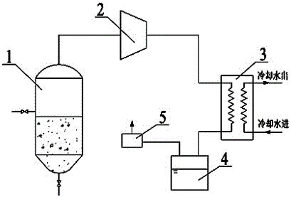
[0018] figure 1 It is the system schematic diagram of this embodiment. As shown in the figure, an isocratic cooling crystallization system includes: a crystallizer 1 , a compressor 2 , a condenser 3 , a condensed water tank 4 , and a vacuum pump 5 . The exhaust port at the top of the crystallizer 1 is connected to the inlet of the compressor 2, the outlet of the compressor 2 is connected to the gas side inlet of the condenser 3, the gas side outlet of the condenser 3 is connected to the inlet of the condensed water tank 4, and the condensed water tank 4 The outlet of the vacuum pump 5 is connected. The compressor 2 is a Roots compressor; the condenser 3 is a plate heat exchanger; the vacuum pump 5 is a water ring vacuum pump. The side wall of the crystallizer 1 is provided with a feed pipe, and the bottom is provided with a discharge pipe.

[0019] When the system is working, first add hot solution to the specified liquid level, turn on the compressor 2 and vacuum pump 5, ...

Embodiment 2

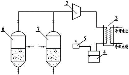
[0021] figure 2 It is the system schematic diagram of this embodiment. As shown in the figure, an isocratic cooling crystallization system includes: a compressor 2 , a condenser 3 , a condensed water tank 4 , a vacuum pump 5 , a first crystallizer 6 , and a second crystallizer 7 . The first crystallizer 6 and the exhaust port at the top of the second crystallizer 7 are all connected to the inlet of the compressor 2, and valves are respectively installed on the connecting pipeline; the compressor 2 outlet is connected to the gas side inlet of the condenser 3, and the condenser The gas side outlet of 3 is connected to the inlet of condensed water tank 4, and the outlet of condensed water tank 4 is connected to vacuum pump 5. The compressor 2 is a screw compressor; the condenser 3 is a shell and tube heat exchanger; the vacuum pump 5 is a water ring vacuum pump. Both the side walls of the first crystallizer 6 and the second crystallizer 7 are provided with feed pipes, and the ...


PUM


Abstract

The invention relates to a constant-gradient cooling crystallization system and an operation method thereof and belongs to the technical field of crystallization. The constant-gradient cooling crystallization system comprises a crystallizer, a compressor, a condenser, a condensation water tank and a vacuum pump; an exhaust of the crystallizer is connected with an entry of the compressor, an exit of the compressor is connected with an air-side entry of the condenser, the air-side entry of the condenser is connected to the condensation water tank, and the vacuum pump is connected to the condensation water tank. By the arrangement that the compressor is taken as vacuum-pumping equipment of the condenser, control on crystal size and cooling rate is realized through matching of compression ratio of the compressor and sucking rate; the constant-gradient cooling crystallization system is simple in structure, few in accessory equipment, convenient in regulating and controlling of crystallization process, and uniform in crystal size.

Description

technical field [0001] The invention relates to a crystallization system, in particular to an equal gradient cooling crystallization system and a working method thereof. Background technique [0002] At present, the crystallization methods used in the industrial field include cooling crystallization, evaporation crystallization and vacuum cooling crystallization. Among them, the cooling crystallization process accounts for about 95% of the application in various domestic industries. The cooling crystallization usually adopts the partition wall cooling method, and the circulating cooling water in the crystallizer jacket reduces the temperature of the solution inside the crystallizer, so that the solution produces a certain degree of supersaturation. And the solution precipitates crystals. Crystals often crystallize on the cooling wall of the cooling crystallization system, forming thickened crystal scars or scales, which not only hinders the heat transfer in the cooling proc...

Claims


Application Information

Patent Timeline
IPC IPC(8): B01D9/02
CPCB01D9/0018B01D9/0063B01D2009/0086B01D2202/00
Inventor 夏君君彭涛
Owner JIANGSU LEKE ENERGY SAVING TECH CO LTD
Learn More