Calibration method for indention load-depth curve of micro-bridge of micro-electro-mechanical system

A micro-electro-mechanical system and calibration method technology, which is applied in the direction of strength characteristics, test material hardness, and measurement devices, can solve the impact of unloading initial point contact stiffness, and can simultaneously test micro-bridge structures, Young's modulus, and hardness calculations. Error and other issues

Active Publication Date: 2017-03-15
JILIN UNIV
View PDF4 Cites 17 Cited by
  • Summary
  • Abstract
  • Description
  • Claims
  • Application Information

AI Technical Summary

Problems solved by technology

Considering that the thickness of the micro-bridge structure is small (a few microns), the measurement of the deflection of such thin-film materials by the nano-indentation test method will cause large errors due to the incompatibility of the indentation depth, which will affect the flexural modulus of the micro-bridge. Accurate evaluation of parameters such as bending strength and fracture deflection
In addition, considering that the indentation process will on the one hand cause the elastic backlog and plastic flow of the material around the indenter contour, on the other hand, the elastic bending of the micro-bridge caused by the indentation load will also affect the actual indented volume, thus produce indentation depths different from the maximum depth value for the elastic semi-infinite space condition
The indentation de

Method used


Image

  • Calibration method for indention load-depth curve of micro-bridge of micro-electro-mechanical system
  • Calibration method for indention load-depth curve of micro-bridge of micro-electro-mechanical system
  • Calibration method for indention load-depth curve of micro-bridge of micro-electro-mechanical system

Examples


Embodiment

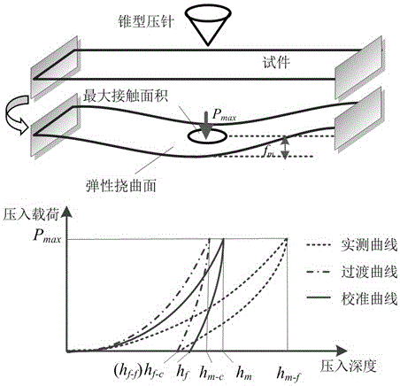
[0028] see Figure 1 to Figure 3 As shown, based on the classic Oliver-Pharr test method and the provisions of ISO14577-1 "Metal Material Hardness and Material Parameter Measurement and Confirmation Test-Part 1: Test Method", when obtaining the indentation load-depth loading and unloading curve (P-h curve ), by obtaining the fitting curve of the maximum indentation depth, residual indentation depth and unloading curve, the parameters such as contact stiffness, hardness and Young's modulus were quantitatively calculated. For the calculation of the contact stiffness S, the unloaded part of the load-depth curve is usually fitted by the least square method as:

[0029] P=α(h-h f ) m (1)

[0030] In the formula, α and m are the fitting parameters related to the tested material, h and h f are the real-time indentation depth and residual depth under the condition of elastic semi-infinite space, respectively. According to the test results of Oliver and Pharr, the value of gain c...


PUM


Abstract

The invention relates to a calibration method for the indention load-depth curve of a micro-bridge of a micro-electro-mechanical system, belonging to the field of testing of the mechanical properties of materials. The bending load-deflection curve and the indention load-depth curve of a micro-bridge structure are synchronously acquired through a nanoindentation test on the micro-bridge structure, wherein the characteristic size of the micro-bridge structure is of a micron order, and two ends of the micro-bridge structure are fixed; and quantitative testing is carried out on the rigidity, Young modulus, hardness, yield stress and breaking strength of a bridge structure of a micro-electro-mechanical system device. Through analysis of a statically indeterminate structure of the micro-bridge, the actual maximum displacement of the tip end of an indenter is accurately parsed to be a sum of the maximum flexural deflection of the micro-bridge and the maximum indention depth of the indenter embedded into the surface of the micro-bridge; and a method for estimating a load-depth curve under the condition of elastic semi-infinite half-space by using the actually-measured indention load-depth curve is established on the basis of both the actual maximum displacement of the indenter and theoretical analysis of maximum depth of indentation by an elastic deflection surface and elastic deflection at the edge of an indentation micro-area; so a novel measuring method is provided for research on the mechanical behaviors of the micro-electro-mechanical system device under stress induction.

Description

technical field [0001] The invention relates to the field of material mechanical performance testing, in particular to a method for calibrating a micro-electromechanical system microbridge indentation load-depth curve, which is applicable to the bending and indentation mechanical performance testing method of the microbridge structure of a microelectromechanical system device. The invention can simultaneously test the bending mechanical properties and indentation response of the microbridge nano-indentation process, can provide data support for silicon micromachining, and can be used for microbeams, Micromechanical properties of microsensors and microactuators provide high-precision testing methods. Background technique [0002] MEMS is a microsystem that integrates the functions of micro-drive, micro-sensing and signal processing. MEMS devices have important applications in sensing, optics, medicine, microelectronics and other fields. The special size of MEMS devices is b...

Claims


Application Information

Patent Timeline
IPC IPC(8): G01N3/42
CPCG01N3/42G01N2203/0082G01N2203/021
Inventor 马志超赵宏伟任露泉马筱溪杜希杰刘长宜周明星
Owner JILIN UNIV
Why Eureka
Try Eureka