High-precision camera dynamic calibration method

A camera calibration and dynamic calibration technology, applied in image analysis, image data processing, instruments, etc., can solve problems such as poor stability and real-time performance, inability to apply to complex backgrounds and large fields of view, and limited calibration accuracy, and achieve good real-time performance. , The method is stable, the effect of high-precision plane motion estimation and measurement

Active Publication Date: 2017-03-15
BEIJING UNIV OF CHEM TECH +1
View PDF2 Cites 17 Cited by
  • Summary
  • Abstract
  • Description
  • Claims
  • Application Information

AI Technical Summary

Problems solved by technology

[0005] In view of the shortcomings of the current camera calibration method that cannot be applied to complex backgrounds and large fields of view, limited calibration accuracy, poor stability and real-time performance, the implementation examples of the present invention provide a high-precision dynamic camera calibration method, including:

Method used


Image

  • High-precision camera dynamic calibration method
  • High-precision camera dynamic calibration method
  • High-precision camera dynamic calibration method

Examples


Embodiment Construction

[0055] In order to solve the problems of limited calibration accuracy, poor stability, unsuitability for complex backgrounds and large field of view conditions, and poor real-time performance of existing camera calibration methods, the present invention provides a high-precision camera dynamic calibration method. The inventive method achieves higher precision for plane motion estimation and measurement, and the present invention will be described in detail below in conjunction with the accompanying drawings and specific implementation examples.

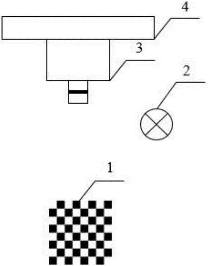
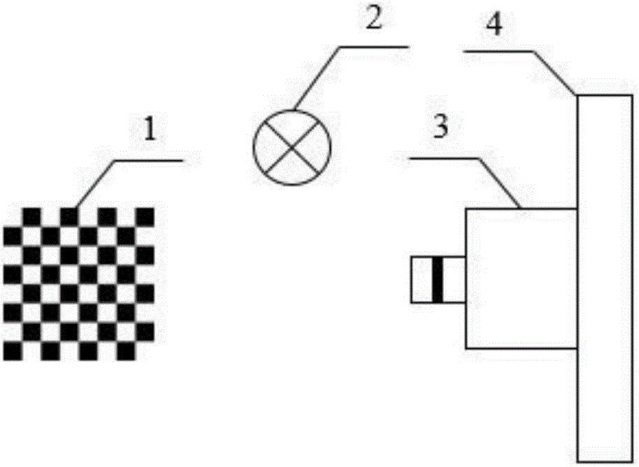
[0056] refer to figure 1 and figure 2 It is a schematic diagram of an implementation example device of the method of the present invention, and the device mainly includes: a camera calibration target 1 , a light source 2 , a visual device 3 , and a vibration isolation table 4 . The vision device 3 is installed on the vibration isolation table 4, the position of the vision device 3 corresponds to the camera calibration target 1, and ...


PUM


Abstract

The invention provides a high-precision camera dynamic calibration method, and belongs to the technical field of image processing and machine vision detection. The method includes detection of checkerboard target image X type calibration points; high-precision positioning of checkerboard target X type calibration points; camera calibration based on non-measurement distortion correction; and camera dynamic calibration. The method is stable, reliable and practical, and is applicable to camera calibration in a simple background and complex background and under a large-visual-field condition at the same time. The method has a simple calibration process and good real-time performance, for a target characteristic area in a sequence image, a user only needs to match a first frame of image target area, only needs arbitrary i frames of single images to complete single-time camera calibration, and a corresponding homography matrix Hi is determined. In the method, parameter coupling does not exist, the whole calibration process only needs to solve and optimize single distortion coefficients. The calibration precision is improved through high-precision positioning of the target calibration points and an optimization method of nonlinear camera imaging model distortion coefficients.

Description

technical field [0001] The invention belongs to the technical field of image processing and machine vision detection, and is especially aimed at high-precision, stable and reliable camera dynamic calibration under complex background and large field of view conditions. Background technique [0002] Camera calibration is the most critical part of machine vision inspection, photographic geometric measurement, etc. The purpose of camera calibration is to determine the internal parameters that characterize the internal optical and geometric characteristics of the camera, as well as the external parameters that characterize the position and direction of the camera coordinate system and the world coordinate system . For planar motion estimation and measurement, it is often not necessary to accurately determine the internal and external parameters of the camera, but only the homography matrix H corresponding to the image coordinates and world coordinates on the moving image. The ca...

Claims


Application Information

Patent Timeline
Patent Type & Authority Applications(China)
IPC IPC(8): G06T7/80
Inventor 王颖杨明蔡晨光刘志华梁东杰
Owner BEIJING UNIV OF CHEM TECH
Why Eureka
Try Eureka