Modularization photovoltaic device

A photovoltaic device and modular technology, which is applied in the field of modular photovoltaic devices, can solve the problems of inability to realize the instant use of photovoltaic modules, low modularity of photovoltaic systems, and difficulty in moving and transporting at will, so as to save manpower and improve construction efficiency. High, easy to fold and transport effect

Active Publication Date: 2017-03-15
湖南红太阳新能源科技有限公司
View PDF5 Cites 1 Cited by
  • Summary
  • Abstract
  • Description
  • Claims
  • Application Information

AI Technical Summary

Problems solved by technology

[0003] (1) The photovoltaic system of the existing technology has a low degree of modularization. The construction of a photovoltaic power station requires site survey, blueprint design, and a series of complicated processes such as bracket installation, component installation, cable laying, and inverter installation. The construction takes a long time , high construction cost
[0004] (2) The structure of the photovoltaic system in the prior art is fixed, and it is not easy to disassemble the components and brackets after the construction is completed, and it is even more difficult to move and transport at will. In extreme weather (such as hail, flood, etc.), the power station cannot be disassembled quickly and moved to a safe place. place
[0005] (3) The photovoltaic system of the existing technology cannot realize the instant increase and use of photovoltaic modules, because a certain number of photovoltaic modules corresponds to a certain capacity of photovoltaic inverters, and if more photovoltaic modules are added, the installed capacity will increase, and the original inverter It will be in an overload state, which will bring risks to the safe operation of the system. It must be replaced with a larger-capacity inverter to work smoothly, and it is inconvenient to quickly expand and reduce capacity.

Method used


Image

  • Modularization photovoltaic device
  • Modularization photovoltaic device
  • Modularization photovoltaic device

Examples


Embodiment Construction

[0035] The present invention will be described in further detail below in conjunction with specific embodiments and accompanying drawings.

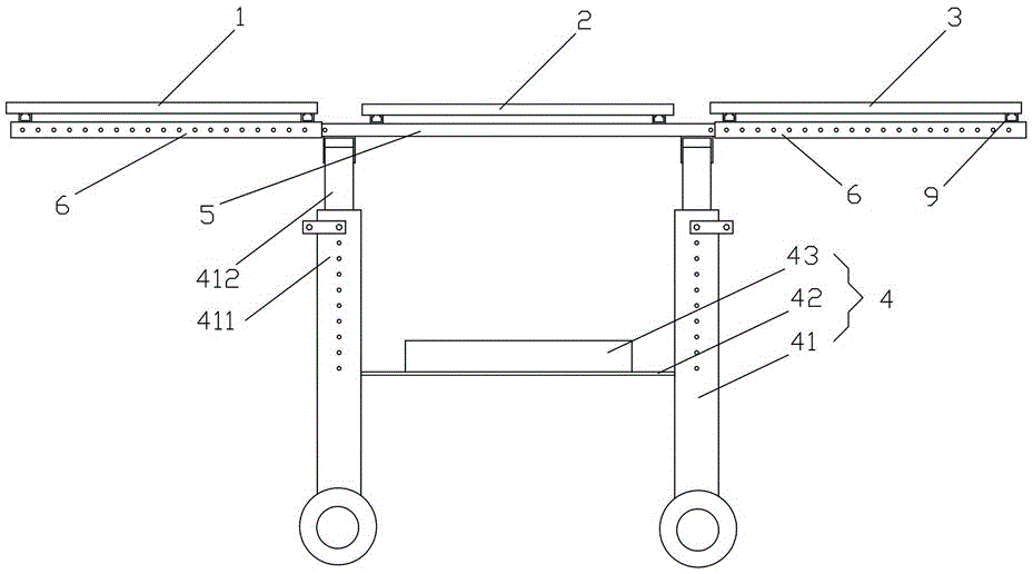
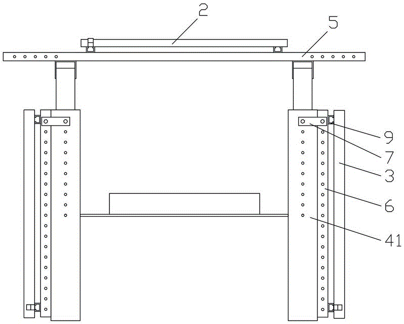
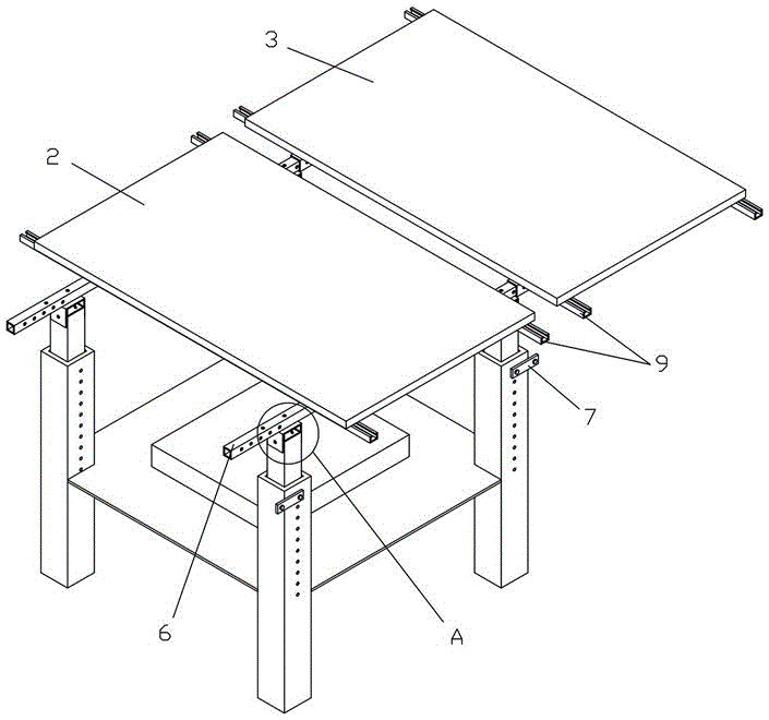
[0036] like Figure 1 to Figure 7As shown, the present invention provides a modular photovoltaic device, including a base 4 and a first photovoltaic assembly 1, a second photovoltaic assembly 2, and a third photovoltaic assembly 3 laid on the base 4 in sequence, and the base 4 includes four Two outrigger assemblies 41, each two outrigger assemblies 41 are respectively provided with a main beam 5, and the two main beams 5 are arranged parallel to each other, and the second photovoltaic module 2 is installed directly above the base 4 through the two main beams 5, The bottom ends of the first photovoltaic module 1 and the third photovoltaic module 3 are provided with two parallel sub-beams 6 . A photovoltaic module 1 and a third photovoltaic module 3 are installed on the left and right sides of the second photovoltaic module 2 respectively....


PUM


Abstract

The invention discloses a modularization photovoltaic device. The modularization photovoltaic device comprises a base; a first photovoltaic component, a second photovoltaic component, and a third photovoltaic component, which are sequentially disposed on the base in a tiled manner. The base comprises four supporting leg components, and each two supporting leg components are respectively provided with a main cross beam, and the two main crossbeams are parallely arranged. The second photovoltaic component is disposed right on the upper part of the base by the two crossbeams, and the bottom end of the first photovoltaic component and the bottom end of the third photovoltaic component are provided with two secondary crossbeams, which are parallel to each other. During installation, the four secondary crossbeams are respectively cooperated with the end parts of the two main crossbeams in a sleeved manner, and then the first photovoltaic component and the third photovoltaic component are respectively disposed on the left side and the right side of the second photovoltaic component in a tiled manner. After dismounting, the four secondary crossbeams are fixedly cooperated with the supporting leg components by more than one fixing members, and then the first photovoltaic component and the third photovoltaic component are respectively vertically and fixedly disposed on the left side and the right side of the base. The modularization photovoltaic device has advantages of simple and compact structure, high modularization degree, and ability of facilitating fast capacity expansion and capacity reduction, fast disassembly and conveying.

Description

technical field [0001] The invention mainly relates to the field of photovoltaic equipment, in particular to a modularized photovoltaic device. Background technique [0002] The distributed photovoltaic power generation system is composed of photovoltaic modules, photovoltaic brackets, combiner boxes, inverters, AC power distribution cabinets and other electrical equipment. The photovoltaic modules are used as power generation equipment and are the core equipment in the system. The photovoltaic modules are installed on the photovoltaic system at a certain angle. On the bracket, the light is converted into direct current under the condition of light, and after being collected by the combiner box, it flows into the inverter. The inverter inverts the direct current into power frequency alternating current, and realizes low-voltage grid connection on the user side through the AC power distribution cabinet. The photovoltaic system of the prior art has the following technical prob...

Claims


Application Information

Patent Timeline
Patent Type & Authority Applications(China)
IPC IPC(8): H02S20/30H02S40/32H02M7/42
CPCY02E10/56H02S20/30H02M7/42H02S40/32
Inventor 杨彪黄超辉何学飞谢建国罗亮
Owner 湖南红太阳新能源科技有限公司
Why Eureka
Try Eureka