
A single-rail current modulus one-bit full adder based on finfet devices

A technology of current mode and full adder, which is applied to logic circuits with logic functions, instruments, and electrical digital data processing, etc. It can solve problems such as circuit logic errors, achieve the effects of increasing stability, simplifying circuits, and avoiding series configuration.

Active Publication Date: 2019-07-19
宁波华盾新能源科技有限公司
View PDF1 Cites 0 Cited by
  • Summary
  • Abstract
  • Description
  • Claims
  • Application Information

AI Technical Summary

Problems solved by technology

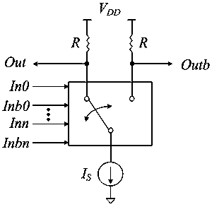
[0004] like figure 1 As shown, the traditional current mode circuit adopts a dual-rail differential structure. Two resistors R are used as pull-up resistors, and a fully differential pull-down network and a current source are connected underneath. In the dual-rail current mode topology, as the input signal increases, the power supply The stack flowing through is too long, because of the input series structure, the closer to the bottom of the FinFET transistor is divided, the smaller the voltage is, and the voltage at this time is likely to be insufficient to meet the normal working voltage requirements of the FinFET tube. The logic of the entire circuit an error occurred

Method used


Image

  • A single-rail current modulus one-bit full adder based on finfet devices
  • A single-rail current modulus one-bit full adder based on finfet devices
  • A single-rail current modulus one-bit full adder based on finfet devices

Examples


Embodiment Construction

[0028] The preferred embodiments of the present invention will be described in detail below with reference to the accompanying drawings.

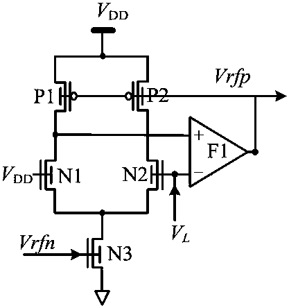
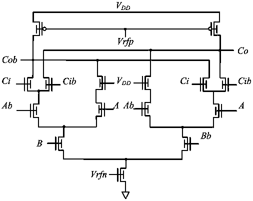
[0029] see figure 2 , shown in Fig. 4 (a) and Fig. 4 (b), it is the circuit of a kind of bias circuit, summation output circuit and carry output circuit of a kind of single-rail current modulus one-bit full adder based on FinFET device of the embodiment of the present invention Schematic diagram, the bias circuit controls the voltage swing, the source of the first P-type FinFET P1, the back gate of the first P-type FinFET P1, the source of the second P-type FinFET P2, the second P-type FinFET The back gate of P2 and the front gate of the first N-type FinFET tube N1 are connected to the power supply voltage VDD, the back gate of the first N-type FinFET tube N1, the back gate of the second N-type FinFET tube N2, and the third N-type FinFET tube The source of N3 and the back gate of the third N-type FinFET transistor N3 are grounded, and the...


PUM


Abstract

The invention discloses a single track current mode one bit full adder based on a FinFET device. The single track current mode one bit full adder comprises a bias circuit, a summation output circuit, and a carry output circuit. The summation output circuit comprises a third P-type FinFET pipe; a fourth P-type FinFET pipe and a fourth N-type FinFET pipe, which are respectively connected with the third P-type FinFET pipe; a fifth N-type FinFET pipe and a sixth N-type FinFET pipe, which are parallely connected together; a seventh N-type FinFET pipe; a ninth N-type FinFET pipe and a tenth N-type FinFET pipe, which are parallely connected together. The fourth N-type FinFET pipe is connected with the fifth N-type FinFET pipe and the sixth N-type FinFET pipe, which are parallely connected together. The seventh N-type FinFET pipe is connected with the fifth N-type FinFET pipe and the sixth N-type FinFET pipe, which are parallely connected together, and is connected with the ninth N-type FinFET pipe and the tenth N-type FinFET pipe, which are parallely connected together. By adopting a differential single track current mode structure, the N-type FinFET pipes in the pull-down network of the single track current mode adopt the parallel connection structures to realize a multi-input NOR function, and the serial connection configuration of the N-type FinFET pipes is prevented, and therefore circuit performance is optimized, and the circuit can still work normally under conditions of standard voltage and superthreshold.

Description

technical field [0001] The invention belongs to the field of electronic circuits, in particular to a single-rail current modulus one-bit full adder based on a FinFET device. Background technique [0002] With the application of integrated circuit chips in electronic products more and more widely, the power consumption of chips has also received great attention. Improving the working speed and reducing the power consumption of chips has become an important goal of many researchers. With the continuous shrinking of the transistor size, the size of the CMOS process has shrunk to the nanometer range which is difficult to further shrink. When the size of ordinary CMOS transistors is reduced to below 20nm, the leakage current of the device will increase sharply, resulting in a large leakage power consumption of the circuit. Moreover, the short-channel effect of the circuit becomes more obvious, and the device becomes quite unstable, which greatly limits the improvement of the cir...

Claims


Application Information

Patent Timeline
Patent Type & Authority Patents(China)
IPC IPC(8): H03K19/20G06F7/501
CPCG06F7/501H03K19/20
Inventor 张霞刘伏亮吴晟姗
Owner 宁波华盾新能源科技有限公司
Learn More