A high-precision robotic automatic welding device for grid plates and its working method

An automatic welding and working method technology, applied in welding equipment, auxiliary devices, auxiliary welding equipment, etc., can solve the problems of difficult to complete the process, cumbersome operation, impossible to achieve, etc., to improve the welding accuracy, improve the welding efficiency, meet the The effect of production and processing requirements

Active Publication Date: 2019-03-12
SUZHOU WST ROBOT AUTOMATION CO LTD
View PDF12 Cites 0 Cited by
  • Summary
  • Abstract
  • Description
  • Claims
  • Application Information

AI Technical Summary

Problems solved by technology

At present, many enterprises use robots for welding, and the cost is relatively high. Because the welding operation of steel grid plates is too cumbersome, and it is not a special customization of welding products, some processes are difficult or impossible to complete. The existing There will be a lot of metal dust in the production environment of steel grating, which will put forward higher requirements for automatic welding equipment, so the existing welding technology of steel grating needs to be improved

Method used


Image

  • A high-precision robotic automatic welding device for grid plates and its working method
  • A high-precision robotic automatic welding device for grid plates and its working method

Examples


Embodiment

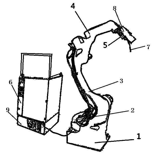
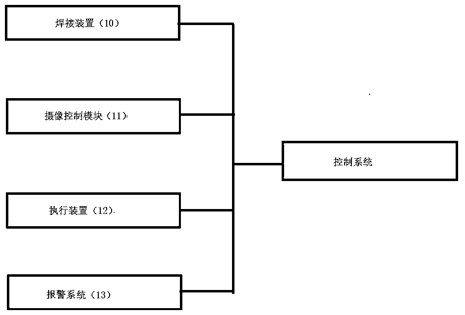
[0044] like figure 1 and figure 2 A high-precision robotic automatic welding device dedicated to grid plates is shown, including: a fixed seat 1, a rotating shaft 2, a lower arm 3, an upper arm 4, a wrist joint 5, and an electric control box 6. In the electric control box 6 An industrial computer 9 is provided, and a control device is provided in the industrial computer 9, and the control device includes a welding device 10, a camera control module 11, an execution device 12, an alarm system 13 and a control system, and the control system 14 There is a single-chip microcomputer control system and controller;

[0045] The relationship between the above components is as follows:

[0046] The rotating shaft 2 is arranged on the fixed seat 1, the lower arm 3 is connected with the rotating shaft 2 through a positioning pin, the upper arm 4 is connected with the lower arm 3 through a positioning pin, and the wrist joint 5 is positioned through a positioning pin. The pin is conne...

Embodiment 2

[0055] like figure 1 and figure 2 A high-precision robotic automatic welding device dedicated to grid plates is shown, including: a fixed seat 1, a rotating shaft 2, a lower arm 3, an upper arm 4, a wrist joint 5, and an electric control box 6. In the electric control box 6 An industrial computer 9 is provided, and a control device is provided in the industrial computer 9, and the control device includes a welding device 10, a camera control module 11, an execution device 12, an alarm system 13 and a control system, and the control system 14 There is a single-chip microcomputer control system and controller;

[0056] The relationship between the above components is as follows:

[0057] The rotating shaft 2 is arranged on the fixed seat 1, the lower arm 3 is connected with the rotating shaft 2 through a positioning pin, the upper arm 4 is connected with the lower arm 3 through a positioning pin, and the wrist joint 5 is positioned through a positioning pin. The pin is conne...


PUM


Abstract

The invention discloses a high-precision robot automatic welding device special for a grid plate. The high-precision robot automatic welding device special for the grid plate comprises a fixed base, a rotating shaft, a lower arm, an upper arm, a wrist joint and an electric control box, wherein the rotating shaft is arranged on the fixed base; the lower arm is connected with the rotating shaft through a positioning pin; the upper arm is connected with the lower arm through a positioning pin; the wrist joint is connected with the upper arm through a positioning pin, and a welding gun and a camera device are arranged at one end of the wrist joint; cameras are arranged in the camera device; the rotating shaft, the lower arm, the upper arm, the wrist joint and the camera device are all electrically connected with an electric control box. According to the high-precision robot automatic welding device special for the grid plate, the camera device is arranged in the automatic welding device; the grid plate which is required to be welded is shot through three groups of cameras; the images shot by the cameras are subjected to data processing and analyzing through a control system in a control device; the type of the grid plate which is required to be welded, a position which is required to be welded and the welding quality are known precisely, so that the welding precision of the automatic welding device is greatly improved.

Description

technical field [0001] The invention belongs to the field of production and manufacturing, and in particular relates to a high-precision robot automatic welding device for grid plates and a working method thereof. Background technique [0002] Steel grating carbon dioxide gas is mainly used for edge sealing of steel grating. Most welding companies still use manual welding for welding. The workload is very heavy. At the same time, due to the large number of people in the welding process Most of them are welded with the naked eye, and the quality of the welding is not stable enough. Due to the poor controllability of people, it is difficult to keep the quality of the welding consistent. Because the welding points are relatively dense, the technical requirements for welding workers are high. The matching of position and parameters is not easy to maintain the best. During the welding process, problems of false welding and missing welding often occur, and the gas generated during...

Claims


Application Information

Patent Timeline
Patent Type & Authority Patents(China)
IPC IPC(8): B23K37/02B23K37/047B25J9/00B25J19/04B25J19/06
CPCB23K37/0252B23K37/047B25J9/00B25J19/04B25J19/061
Inventor 张敏强
Owner SUZHOU WST ROBOT AUTOMATION CO LTD
Why Eureka
Try Eureka