
Energy storage tram control system and tram with the same

A control system and trolley technology, which is applied to the energy storage trolley control system and trolley. It can solve the problems of difficulty in releasing large power, poor regeneration and feedback energy, and short battery life, so as to achieve the effect of improving energy utilization efficiency, good acceleration performance and stable power

Inactive Publication Date: 2017-03-22
ZHUZHOU ELECTRIC LOCOMOTIVE CO
View PDF7 Cites 12 Cited by
  • Summary
  • Abstract
  • Description
  • Claims
  • Application Information

AI Technical Summary

Problems solved by technology

[0004] Most of the existing technologies use lithium batteries as energy storage power sources. Lithium batteries have high energy density and can meet the requirements of vehicle cruising range, but the charging and discharging current is too small to release large power, especially in manufacturing In the dynamic link, the effect of regenerative energy feedback is poor, and the service life of the battery is short
[0005] In addition to lithium batteries, electric vehicles using fuel cells as energy storage power sources have the advantages of high efficiency and environmental protection, but the response speed of fuel cells is slow, which cannot match the actual operating conditions of the vehicle, and also has short service life and failure to achieve braking. energy feedback problem
[0006] The energy storage power supply using supercapacitors as energy storage components solves the problems of service life and high-current charging and discharging. However, since supercapacitors are power devices, their energy density is low and cannot meet the requirements of vehicle cruising range.

Method used


Image

  • Energy storage tram control system and tram with the same

Examples


Embodiment Construction

[0027] The following will clearly and completely describe the technical solutions in the embodiments of the present invention with reference to the accompanying drawings in the embodiments of the present invention. Obviously, the described embodiments are only some, not all, embodiments of the present invention. Based on the embodiments of the present invention, all other embodiments obtained by persons of ordinary skill in the art without making creative efforts belong to the protection scope of the present invention.

[0028] The core of the present invention is to provide an energy storage tram control system, which has a strong battery life and can realize energy recovery and utilization. Another core of the present invention is to provide an electric vehicle including the above-mentioned energy storage electric vehicle control system.

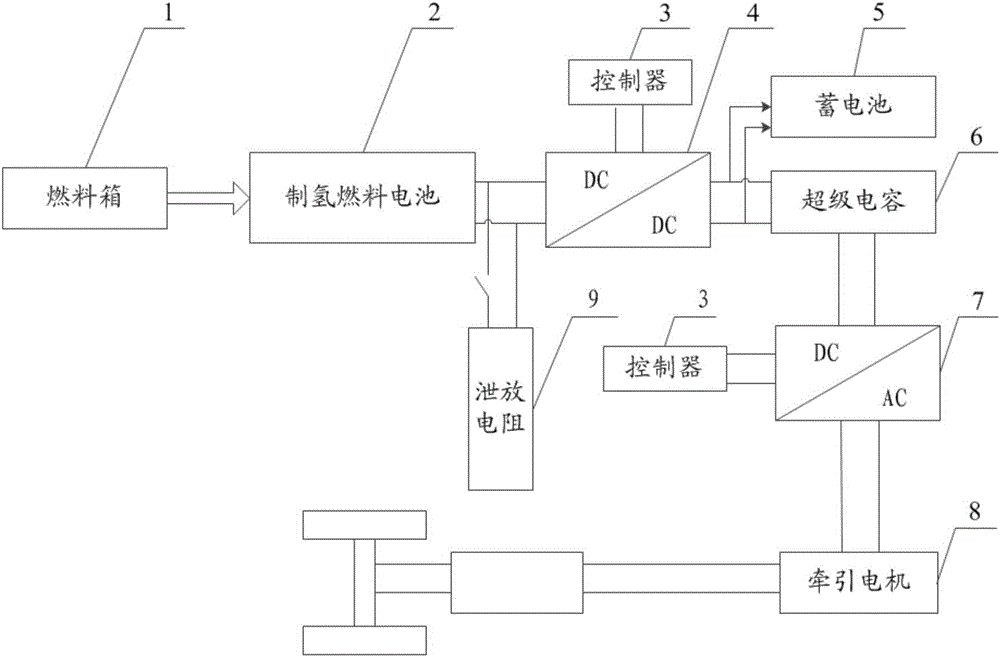
[0029] Please refer to figure 1 , figure 1 It is a schematic diagram of a specific embodiment of the energy storage electric vehicle co...


PUM


Abstract

The invention discloses an energy storage tram control system. The energy storage tram control system comprises a hydrogen-producing fuel cell, a super-capacitor and a bleeder resistor which is used for bleeding the super-capacitor when the super-capacitor is over-voltage, wherein the hydrogen-producing fuel cell is connected with the super-capacitor through a direct current chopper; the super-capacitor is connected with a traction motor of a vehicle through an inverter; the direct current chopper and the inverter are both connected with a controller; and the controller is used for controlling the super-capacitor to provide power to the traction motor and controlling the super-capacitor to absorb braking energy of the traction motor. As the energy storage tram control system disclosed by the invention drives the traction motor through the super-capacitor, the vehicle can obtain good acceleration performance, the bleeder resistor can be used for bleeding the super-capacitor when the super-capacitor is over-voltage, and the controller can feed back and absorb the braking energy in each vehicle braking process; therefore, the energy utilization efficiency is increased and energy is saved. The invention further discloses a tram including the energy storage tram control system.

Description

technical field [0001] The invention relates to the technical field of electric vehicle design, and more specifically, relates to an energy storage electric vehicle control system. In addition, the present invention also relates to an electric vehicle comprising the above energy storage electric vehicle control system. Background technique [0002] At present, most of the cars on the road use gasoline or diesel fuel extracted from crude oil. Compared with internal combustion vehicles powered by fossil energy, electric vehicles have significant advantages in environmental protection and energy saving. Electric vehicles include pure electric vehicles, hybrids Power vehicles and fuel cell vehicles. [0003] There are several schemes for the energy storage power supply of new energy vehicles that use lithium batteries, fuel cells or supercapacitors as energy storage components. At home and abroad, some achievements have been made in the design of electric vehicle energy storag...

Claims


Application Information

Patent Timeline
IPC IPC(8): B60L11/00B60L11/18B60L7/10
CPCB60L7/10B60L50/40B60L50/50B60L58/30Y02T10/70Y02T10/72Y02T90/40
Inventor 彭钧敏毛业军杨颖邓谊柏阳涛杜求茂张伟先
Owner ZHUZHOU ELECTRIC LOCOMOTIVE CO
Learn More