
Oil-saving type swirling flow burner port ignition device of W-type boiler

An ignition device and a technology of flowing fire, which are applied in the direction of ignition by guiding the flame, combustion ignition, combustion type, etc., can solve the problems of weak ignition effect of oil flame, long distance, large fuel consumption of W-type boiler ignition, etc., and achieve fog The effect of improving the burnout degree of pulverized coal is excellent

Pending Publication Date: 2017-03-22
WUHAN SIQI ENVIRONMENTAL PROTECTION TECH CO LTD +1
View PDF5 Cites 0 Cited by
  • Summary
  • Abstract
  • Description
  • Claims
  • Application Information

AI Technical Summary

Problems solved by technology

Due to structural reasons, the existing burner ignition devices of W-type boilers are all arranged on the side of the pulverized coal nozzle, and the distance from the pulverized coal nozzle is relatively long. The contact part between the flame of the burner ignition device and the pulverized coal airflow is less than 1 / 3, the ignition effect of the oil flame on the pulverized coal is not strong, which leads to the prominent problem of large fuel consumption for W-type boiler ignition

Method used


Image

  • Oil-saving type swirling flow burner port ignition device of W-type boiler
  • Oil-saving type swirling flow burner port ignition device of W-type boiler
  • Oil-saving type swirling flow burner port ignition device of W-type boiler

Examples


Embodiment Construction

[0014] The present invention will be further described in detail below in conjunction with the accompanying drawings and specific embodiments.

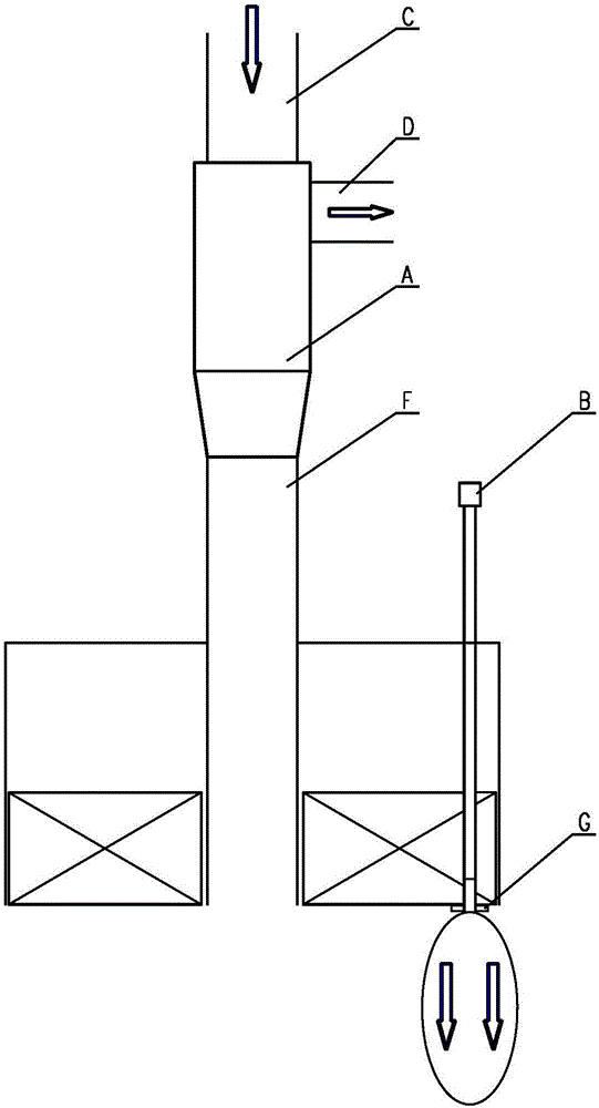
[0015] figure 1 It is a structural schematic diagram of an existing oil gun ignition device for a W-type boiler, and its structure has been described above, and will not be repeated here.

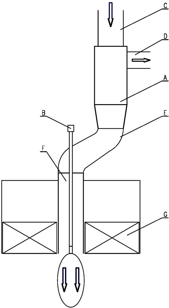
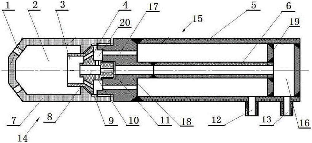
[0016] Figure 2~3 The oil-saving swirling burner ignition device for a W-type boiler shown in , includes a pulverized coal concentration separator A and an ignition spray gun B. One end of the pulverized coal concentration separator A is provided with a primary air inlet C, and its side wall is provided with an exhaust gas outlet. D. The other end of the pulverized coal concentration separator A is connected to the swirling nozzle F through an elbow connecting pipe E. The bending part of the elbow connecting pipe E is interspersed with an ignition spray gun B, and the ignition spray gun B is the same as the central tube of the swirling nozzle F. ...


PUM

PropertyMeasurementUnit
Angleaaaaaaaaaa

Abstract

The invention discloses an oil-saving type swirling flow burner port ignition device of a W-type boiler. The oil-saving type swirling flow burner port ignition device comprises a coal dust rich-lean separator and an ignition spraying gun, wherein a primary air inlet is formed in one end of the coal dust rich-lean separator, and an exhaust gas outlet is formed in the side wall of the coal dust rich-lean separator; the other end of the coal dust rich-lean separator is connected with a swirling flow burner port through an elbow connection pipe; the ignition spraying gun is arranged at the bent part of the elbow connection pipe; one end of the ignition spraying gun extends out of the elbow connection pipe, and the other end of the ignition spraying gun extends to a coal dust spraying opening and is flush with the coal dust spraying opening; the ignition spraying gun comprises a gun head and a gun body; the gun head is provided with an air bubble chamber and a spraying nozzle located at the end part of the air bubble chamber; the tail end of the gun head is connected with the gun body through an oil-gas distributor; the oil-gas distributor is equipped with an oil spraying nozzle, a vortex chamber and an energy gathering chamber which are coaxially connected with one another in sequence from tail to head; an inner pipe and an outer pipe which are isolated from each other are coaxially arranged in the gun body; the inner pipe and the outer pipe are respectively connected with an oil inlet and an atomized air inlet; a tail cavity is formed in the tail part of the gun body; the tail cavity respectively communicates with the inner pipe and the oil inlet; and the tail cavity is isolated from the outer pipe through a tail ring.

Description

technical field [0001] The invention relates to components on a W-type boiler, in particular to an oil-saving swirl burner ignition device for a W-type boiler. Background technique [0002] W-type boilers generally use anthracite coal, which has very poor ignition performance and pulverized coal is not easy to ignite. This has led to the fact that the W-type boiler must burn a large amount of fuel oil during the start-up phase, most of which are expensive light diesel oil. After the furnace temperature is heated to a very high temperature, the pulverized coal can be ignited normally. A 600MW-class W-type boiler consumes about 120 tons of fuel for ignition, and the ignition cost is very high. Due to structural reasons, the existing burner ignition devices of W-type boilers are all arranged on the side of the pulverized coal nozzle, and the distance from the pulverized coal nozzle is relatively long. The contact part between the flame of the burner ignition device and the pul...

Claims


Application Information

Patent Timeline
IPC IPC(8): F23Q9/00F23D1/02
CPCF23D1/02F23Q9/00
Inventor 王兴俊刘璐施金汉江兴张永利任礼刚后颖黎岳杨王贤杨章宁黄际兵马为民齐惠乔永成张文龙
Owner WUHAN SIQI ENVIRONMENTAL PROTECTION TECH CO LTD
Learn More