Energy concentrating assembly of gas stove
A gas stove and energy-gathering technology, applied in the field of gas stoves, can solve problems such as improvement, increase in nitrogen oxide generation, decrease in combustion efficiency, etc., and achieve the effects of improved capacity, reduction of nitrogen oxides, and improvement of combustion efficiency
- Summary
- Abstract
- Description
- Claims
- Application Information
AI Technical Summary
Problems solved by technology
Method used
Image

Examples
Embodiment Construction
[0022] The present invention will be further described in detail below in conjunction with the accompanying drawings and embodiments.
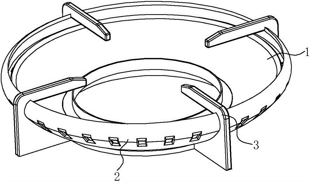
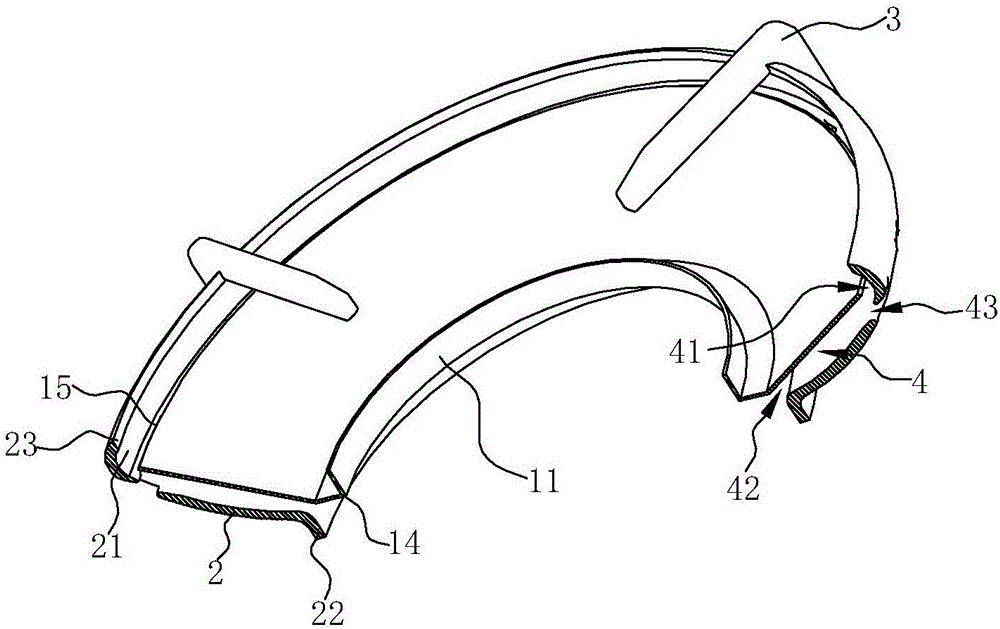
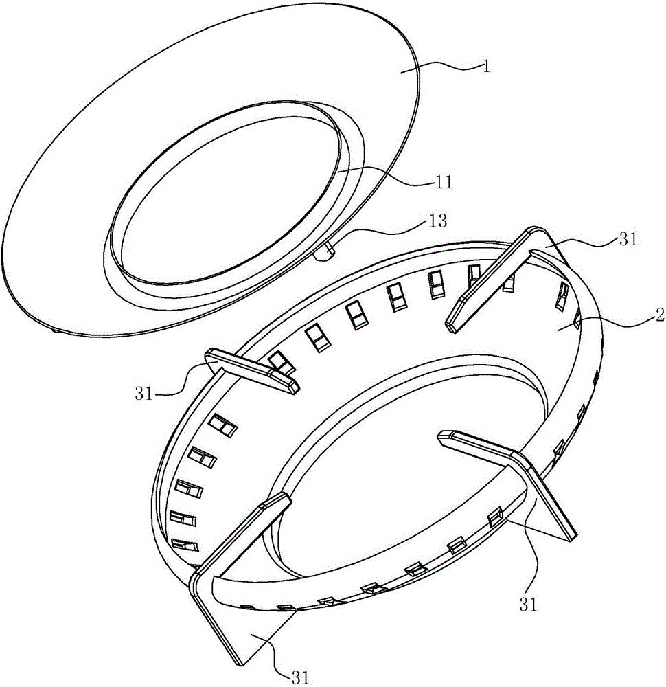
[0023] see Figure 1 ~ Figure 4 , an energy gathering assembly of a gas stove, comprising a first energy gathering cover 1 , a second energy gathering cover 2 and a pot support 3 . The first energy gathering cover 1 and the second energy gathering cover 2 are all annular, and the inner edge 14 of the first energy gathering cover 1 is lower than the outer edge 15, and the inner edge 22 of the second energy gathering cover 2 is also lower than the first Two outer edges 23 of the energy gathering cover 2 .
[0024] The first energy-gathering cover 1 is arranged on the inside of the second energy-gathering cover 2, and the pot support 3 is arranged on the second energy-gathering cover 2 to form a whole. In this embodiment, the pot support 3 includes a plurality of legs 31, and each leg 31 extends on the peripheral wall surface of the second ener...
PUM
 Abstract
Description
Claims
Application Information
 - Generate Ideas
- Intellectual Property
- Life Sciences
- Materials
- Tech Scout
- Unparalleled Data Quality
- Higher Quality Content
- 60% Fewer Hallucinations
Browse by: Latest US Patents, China's latest patents, Technical Efficacy Thesaurus, Application Domain, Technology Topic, Popular Technical Reports.
© 2025 PatSnap. All rights reserved.Legal|Privacy policy|Modern Slavery Act Transparency Statement|Sitemap|About US| Contact US: help@patsnap.com