
Frequency stabilization apparatus and method for laser interferometer

A laser interferometer and frequency stabilization technology, which is applied in the direction of using optical devices, lasers, measuring devices, etc., can solve the problems of difficulty in controlling the ratio of the S light component and the P light component, affecting the frequency stabilization accuracy, etc., and achieves a simple and easy structure. , Increase the laser intensity, the effect of easy mechanical packaging

Inactive Publication Date: 2017-03-22
CHOTEST TECH INC
View PDF6 Cites 3 Cited by
  • Summary
  • Abstract
  • Description
  • Claims
  • Application Information

AI Technical Summary

Problems solved by technology

[0008] 1. Using the thermal frequency stabilization method of taillight frequency stabilization, it is inevitable that there will be some stray light, which will affect the accuracy of frequency stabilization
[0009] 2. The effect of using part of the working light to stabilize the frequency is good, but the ratio of light splitting in the frequency stabilization and the ratio of the S light component and the P light component in the split light are difficult to control

Method used


Image

  • Frequency stabilization apparatus and method for laser interferometer
  • Frequency stabilization apparatus and method for laser interferometer
  • Frequency stabilization apparatus and method for laser interferometer

Examples


Embodiment Construction

[0028] The present invention will be further described below in conjunction with the accompanying drawings and specific embodiments.

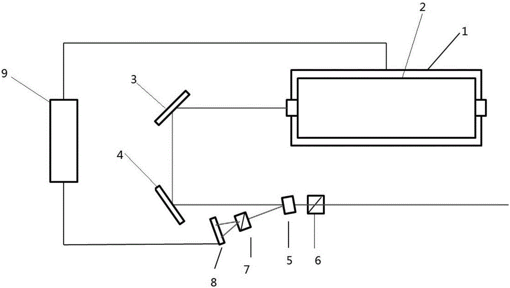
[0029] Figure 3 to Figure 5 The reference numbers in the figure are: frequency stabilizing cavity 1; laser 2; first total reflection mirror 3; incident surface 51; transmission surface 52; second total reflection mirror 4; first beam splitter 5; Two beam splitters 7; photocell 8; circuit control system 9.

[0030] The purpose of the present invention is as follows:

[0031] 1. Through the design of frequency stabilization and splitting optical path, the proportion of light used for frequency stabilization in the laser is very small.

[0032] 2. Through the design of the frequency stabilization splitting optical path and device structure, the light intensity of S light and P light used in frequency stabilization is basically equal.

[0033] 3. Achieve high-precision light splitting by using ordinary optical devices, so that it can be used in...


PUM


Abstract

The invention provides a frequency stabilization apparatus for a laser interferometer. The frequency stabilization apparatus comprises a circuit control system, a laser, a guiding light path, a frequency-stabilizing light path, and a laser output light path. The guiding light path guides light emitted by the laser to the frequency-stabilizing light path. And the frequency-stabilizing light path consists of a first spectroscope, a second spectroscope, and a photocell. In addition, the invention also provides a frequency stabilization method for a laser interferometer. The apparatus and the method have the following beneficial effects: on the basis of the design of frequency-stabilizing light splitting, the proportion of light for frequency stabilization in the laser is low, so that the energy loss of the frequency-stabilizing part is extremely low and thus the working laser strength is enhanced substantially; because of the angle and dimension design of the first spectroscope, the influence on the frequency-stabilizing precision by stray light can be reduced substantially; the frequency-stabilizing light splitting adjustment becomes convenient; the structure is simple and is easy to implement; the structure is compact and is easy to mechanical packaging; and the precision and reliability of frequency-stabilizing data can be guaranteed based on the symmetric optic and electronic design.

Description

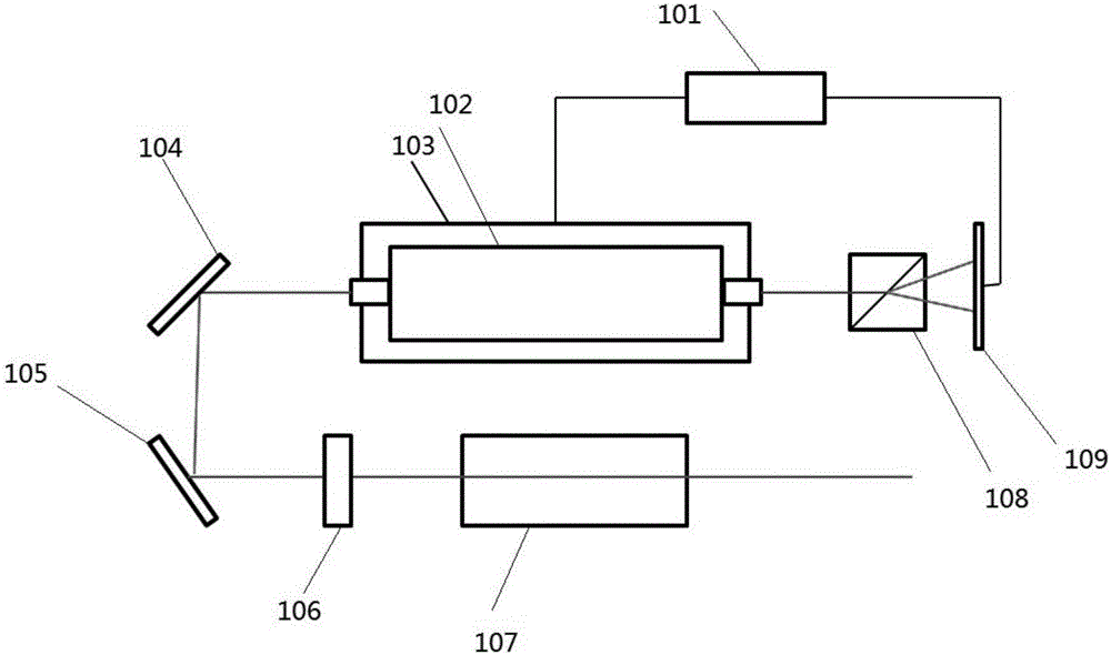
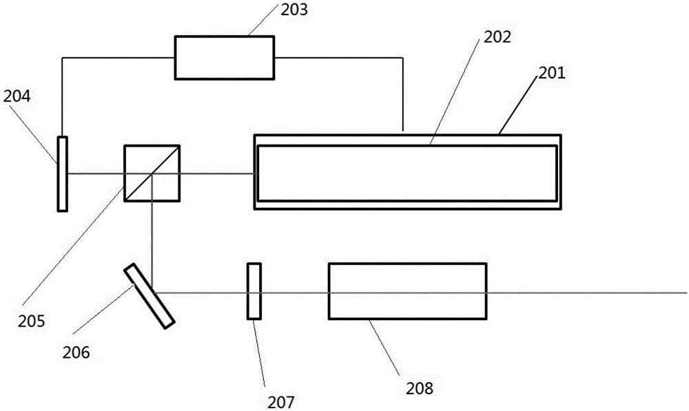
technical field [0001] The invention relates to a frequency stabilizing device, in particular to a frequency stabilizing device and method for a laser interferometer. Background technique [0002] A laser interferometer is an optical measuring instrument that uses light wave interferometry to measure linear displacement. The frequency-stabilized laser is the core component, and the frequency-stabilized performance of the laser is directly related to the performance of the entire instrument. At present, there are mainly the following methods for laser frequency-stabilized, such as figure 1 and figure 2 shown. [0003] The frequency-stabilized laser is mainly to stabilize the cavity length of the laser. The general method is to use a part of the output light intensity of the laser as feedback, monitor the change of its output through a photodetector, or actively or passively adjust the working cavity length of the laser. In our industrial lasers, especially helium-neon las...

Claims


Application Information

Patent Timeline
Patent Type & Authority Applications(China)
IPC IPC(8): G01B9/02H01S3/137
CPCG01B9/02015H01S3/137
Inventor 刘龙为张和君
Owner CHOTEST TECH INC
Learn More