Integrated multibeam echo sounding device

A multi-beam and sounding technology, applied in the fields of underwater surveying and mapping and underwater survey, can solve the problems of complicated operation, high operator requirements, complex multi-beam sounding system, etc., to achieve novel design and high technical content. Effect

Inactive Publication Date: 2017-03-22
BEIJING HYDRO TECH MARINE TECH CO LTD
12 Cites 11 Cited by

AI-Extracted Technical Summary

Problems solved by technology

The main reason is that the composition of the multi-beam sounding system is extremely complex. In addition to the multi-beam sounding sonar, additional positioning equipment, attitude measurement equipment, and sound velocity measurement devices are required. Complicated pre-test calibration and installation deviation and sonar draft, etc., so pre-test preparations are complicated and require high requirements for operators
[0006] For the fields of fine 3D surveying and mapping of underwater terrain, various underwater structures, and pipelines, especially th...

Abstract

The invention discloses an integrated multibeam echo sounding device, and belongs to the field of underwater survey. In particular, the device comprises the three parts, an underwater acoustic system, an overwater signal processing machine and a control computer. The device has the biggest characteristics that the information gathering specially devised in the underwater acoustic system together with a control unit and a synchronous signal creation unit achieves a real time gathering of sonar data, surface velocity data, attitude data, hydrostatic pressure and temperature data fully synchronously, meanwhile the data are transferred on a real time basis to the overwater signal processing machine and merge organically with the GNSS (Global Navigation Satellite System) and the pressure data, thereby achieving the simultaneous, isospace and isoattitude gathering and processing of all the data. The device can achieve high precision underwater surveying and mapping without the need to cooperate with extra sensors or extra calibration process when in use, can be widely applied to fields of underwater landform and various underwater structures, fine three dimensional mapping of pipelines and the like, and can rapidly achieve the measurement of underwater three dimensional landforms.

Application Domain

Measuring open water depthWater resource assessment +1

Technology Topic

Echo soundingSpeed of sound +13

Image

  • Integrated multibeam echo sounding device
  • Integrated multibeam echo sounding device
  • Integrated multibeam echo sounding device

Examples

  • Experimental program(1)

Example Embodiment

[0025] Specific implementation plan
[0026] The present invention will be further described below in conjunction with the drawings and a preferred embodiment of the present invention.
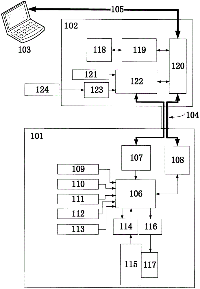
[0027] As a preferred embodiment of the present invention, in the integrated multi-beam sounding device, the acoustic center operating frequency can be selected as 400kHz, and the multi-channel receiving transducer array (115) is realized with a 96-element linear array structure. With a spacing of 1.875mm, each array element forms a horizontal 150° vertical 30° receiving directional beam, so that the natural directivity of the whole array is a uniform receiving linear array of horizontal 1° vertical 30°; multi-channel transmitting transducer array (117 ) Adopts a linear array structure composed of 8-element U-shaped array elements, the distance between the array elements is 22.5mm, and each transmitting array element forms a horizontal 150° vertical 8° transmitting directional beam, multi-channel transmitting transducer array (117) full The natural directivity formed by the array is 150° horizontally and 1° vertically.
[0028] As a preferred embodiment of the present invention, the acoustic center working frequency of the integrated multi-beam sounding device can also be selected as 200kHz, and the multi-channel receiving transducer array (115) is realized with a 96-element linear array structure. The element spacing is 3.75mm, and each element forms a horizontal 160° vertical 30° receiving directional beam, so that the natural directivity of the whole array is a uniform receiving linear array of horizontal 1° vertical 30°; multi-channel transmitting transducer array ( 117) All adopt 24-element U-shaped array elements with a linear array structure. The distance between the array elements is 15mm. Each transmitting array element forms a horizontal 160° vertical 24° transmitting directional beam. The multi-channel transmitting transducer array (117) The natural directivity formed by the array is 160° horizontally and 1° vertically;
[0029] As a preferred embodiment of the present invention, the multi-channel receiving transducer array (115) and the multi-channel transmitting transducer array (117) are combined to form a T-shaped structure, and the electronic warehouse of the underwater acoustic system uses TC4 titanium Made of alloy material or 316L stainless steel material.
[0030] As a preferred embodiment of the present invention, the signal processing unit (118) located in the maritime signal processor (102) consists of two groups Figure 7 The Cyclone III series FPGA module shown is completed with a piece of TI's TMS320C6678 series DSP. The original data distribution module (201), the echo signal preprocessing module (202), the surface sound velocity preprocessing module (203), and the attitude information preprocessing module (204) are implemented by a group of FPGA modules through logic; time delay focused beamforming The module (205) is implemented by a group of FPGA modules through logic; the water body information extraction module (206), the echo intensity extraction module (207), and the real-time terrain detection module (208) are implemented by the TMS320C6678 DSP chip through embedded programs.
[0031] As a preferred embodiment of the present invention, the communication and control unit (122) located in the maritime signal processor (102) is also controlled by Figure 7 The Cyclone III series FPGA module shown is implemented; the network communication unit 1 (119) and the network communication unit 2 (108) are composed of Figure 5 The W5300 network processing chip shown is implemented.
[0032] As a preferred embodiment of the present invention, the synchronization signal generation unit (107) and the information acquisition and control unit (106) in the underwater acoustic system (101) consist of a set Figure 7 The Cyclone III series FPGA module shown is realized by logic; the sound velocity sensor (109), temperature sensor (110), pressure sensor (111), attitude sensor (112), compass (113) are all connected to FPGA through the general IO interface of FPGA Realize data communication.
[0033] As a preferred embodiment of the present invention, the instruction parsing module (301), the multi-channel delay control module (303), and the signal generation module (304) in the multi-channel array signal generating unit (116) are composed of Figure 7 The Cyclone III series FPGA module shown is realized through logic; the programmable power module (302) adopts Image 6 The program-controlled voltage source shown is realized by MAX6495, IRFI4110GPBF and X9C103, which provides power for the power amplifier module (305) realized by standard class D power amplifier.
[0034] The above is only a preferred and feasible embodiment of the invention, and the embodiment is not used to limit the scope of patent protection of the invention. Therefore, any equivalent structural changes made using the contents of the description and drawings of the invention are the same. All should be included in the protection scope of the present invention.

PUM

no PUM

Description & Claims & Application Information

We can also present the details of the Description, Claims and Application information to help users get a comprehensive understanding of the technical details of the patent, such as background art, summary of invention, brief description of drawings, description of embodiments, and other original content. On the other hand, users can also determine the specific scope of protection of the technology through the list of claims; as well as understand the changes in the life cycle of the technology with the presentation of the patent timeline. Login to view more.

Similar technology patents

Wood-plastic wallboard laying structure

Owner:ANHUI SENTAI WPC GRP CO LTD

Feed mechanism of refractory matter processing equipment

InactiveCN107500158Arun smoothlyInnovative design
Owner:长兴金石耐火材料科技有限公司

Classification and recommendation of technical efficacy words

  • High technical content
  • Innovative design

Preparation of crust oligosaccharide and use

InactiveCN1425696AIncrease added valueHigh technical content
Owner:上海华宝孔雀香精有限公司

Compound biological enzyme deodorant and preparation method thereof

InactiveCN102526781ARigorous production process designHigh technical content
Owner:江苏晨翔环境科技股份有限公司

Technique of preparing superfine functional talcum powder

InactiveCN101497748AIncreased Mix AffinityHigh technical content
Owner:马洪新

Paper sheet input method and device

InactiveCN1290751CHigh technical contentSimple equipment structure
Owner:CHINA BANKNOTE PRINTING & MINTING

Complex compound obtained by complexing calcium twice

InactiveCN107873969Aimprove absorbencyHigh technical content
Owner:TIANE HONGCHANG AGRI MACHINERY SPECIALIZED COOP

Polishing device for dustless building grounds

Owner:CHANGSHA WUDAO IND DESIGN CO LTD
Why Eureka
Try Eureka