
Method for adding current traveling wave signal acquisition to transmission line matching device

A technology of transmission lines and current traveling waves, which is applied in the direction of fault location and fault detection according to conductor type, etc., which can solve the problems of low sampling resolution, low signal-to-noise ratio, increasing the complexity and load of on-site CT circuits, etc.

Inactive Publication Date: 2017-03-22
CHINA SOUTHERN POWER GRID COMPANY +2
View PDF6 Cites 6 Cited by
  • Summary
  • Abstract
  • Description
  • Claims
  • Application Information

AI Technical Summary

Problems solved by technology

[0004] The technical problem to be solved by the present invention is to study a method for conveniently, reliably and effectively increasing the current traveling wave signal acquisition on the supporting device of the transmission line, so as to avoid the influence of the traveling wave acquisition circuit on the external AC input interface of the device, and avoid the traveling wave The acquisition circuit increases the complexity and load of the on-site CT circuit, avoids the traveling wave acquisition circuit from affecting the reliability of the original power frequency signal acquisition circuit, and avoids the low signal-to-noise ratio and low sampling resolution caused by the small amplitude of the traveling wave signal

Method used


Image

  • Method for adding current traveling wave signal acquisition to transmission line matching device
  • Method for adding current traveling wave signal acquisition to transmission line matching device
  • Method for adding current traveling wave signal acquisition to transmission line matching device

Examples


Embodiment Construction

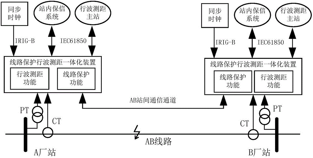
[0015] The embodiment of the present invention provides a method for adding traveling wave signal acquisition in a power transmission line supporting device, and the method can be applied to a power transmission line supporting device such as a power transmission line protection device and a fault recording device. The application scenarios of the transmission line protection device integrated with the traveling wave ranging function according to this method are as follows: figure 1 shown.

[0016] The specific implementation manner of the embodiment of the present invention is as follows:

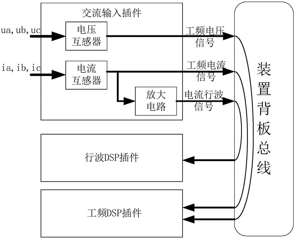
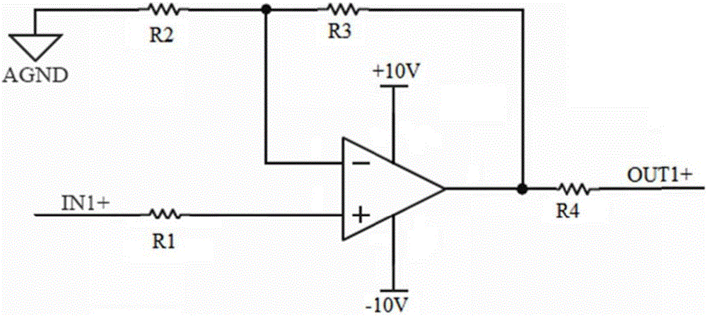
[0017] On the basis of the hardware and software of the conventional power transmission line supporting device, the external hardware interface of the device remains unchanged, and a signal amplification circuit is added to the secondary side of the transformer in the device to realize the amplification of the traveling wave signal, and the traveling wave DSP plug-in is added to the device...


PUM


Abstract

The invention discloses a method for adding current traveling wave signal acquisition to a transmission line matching device. On the basis of the software and hardware of a conventional power transmission line support device, the external hardware interface of the device is maintained to be unchanged, a signal amplifying circuit is added to a current transformer secondary side in the device to realize traveling wave signal amplification, and the amplified traveling wave signal is outputted to a newly added traveling wave DSP plug-in through a device backplane to carry out traveling wave signal collection. The full ranges of a traveling wave signal amplification circuit and a traveling wave DSP plug-in collection circuit are designed according to a four-time overload capacity, and a signal which exceeds a full range is subjected to amplitude limiting. The method can be applied to a transmission line matching device of conventional sampling such as a transmission line protection device and a fault recording device, a traveling wave signal acquisition function can be conveniently, reliably and effectively added, and the signal noise ratio and resolution of the traveling wave signal can be effectively improved.

Description

technical field [0001] The invention relates to power grid protection and automation technology, in particular to a technology for increasing traveling wave signal collection on a power transmission line supporting device. Background technique [0002] At present, both transmission line protection devices and fault recording devices use impedance method for fault location. This method is easily affected by system operation mode, transition resistance, attenuated DC component and measurement error, and it is difficult to achieve accurate fault location. An effective way to improve the accuracy of line fault location is to add the function of current traveling wave fault location to the supporting equipment of the transmission line, so that the monitored line can realize double-terminal traveling wave fault location and single-terminal traveling wave fault location. However, the current conventional transmission line supporting devices, such as transmission line protection dev...

Claims


Application Information

Patent Timeline
IPC IPC(8): G01R31/08
CPCG01R31/085
Inventor 丁晓兵陈玉林史泽兵刘千宽张弛李广宇徐晓春陈宏山陈朝晖李响赵青春朱晓彤王亮侯学勇
Owner CHINA SOUTHERN POWER GRID COMPANY
Learn More