
Pulse time synchronization system for quantum enhanced laser detection

A technology of laser detection and pulse time, which is applied in the field of quantum enhanced laser detection, can solve the problems of optical path difference, optical path difference cannot be compensated, and cannot be synchronized, and achieve the effects of small size, flexible modulation, and low cost

Active Publication Date: 2017-03-22
BEIJING RES INST OF SPATIAL MECHANICAL & ELECTRICAL TECH
View PDF5 Cites 19 Cited by
  • Summary
  • Abstract
  • Description
  • Claims
  • Application Information

AI Technical Summary

Problems solved by technology

However, the signal light pulse is emitted by the quantum-enhanced laser radar transmitter, and has a different path from the local pump light pulse and local oscillator light pulse, and there is an optical path difference. Measures need to be taken to eliminate the asynchronous problem caused by the optical path difference
Since the pump light pulse and the signal light pulse have the same source, they cannot be synchronized by cavity lock
Moreover, the optical path difference caused by different paths cannot be compensated by the all-optical method based on optical parametric amplification

Method used


Image

  • Pulse time synchronization system for quantum enhanced laser detection
  • Pulse time synchronization system for quantum enhanced laser detection
  • Pulse time synchronization system for quantum enhanced laser detection

Examples


Embodiment Construction

[0021] The present invention will be described in detail below in conjunction with the accompanying drawings and embodiments.

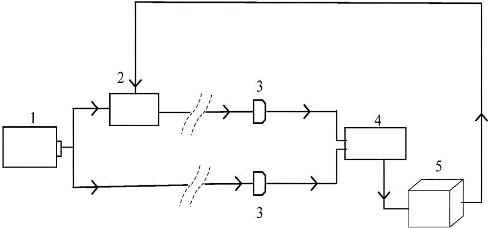
[0022] The invention describes a pulse time synchronization system for quantum-enhanced laser detection, which can promote homologous pump light, signal light and local oscillator light to achieve time synchronization at a nonlinear crystal or a balanced zero-beat detector.

[0023] Such a pulse-time-synchronized system for quantum-enhanced laser detection such as figure 1 As shown, it includes a main laser light source 1, a delay unit 2, a time synchronization monitoring detector 3, a digital phase-lock unit 4 and a synchronization control unit 5, wherein the main laser light source 1 is divided into two beams by a beam splitter, and one beam is used as Local oscillator light and pump light, one beam is used as signal light; delay unit 2 is located in the optical path of local oscillator light and pump light, and is used to change the optical path of...


PUM


Abstract

The invention provides a pulse time synchronization system for quantum enhanced laser detection. The system comprises a laser main light source (1), a delay unit (2), a time synchronization monitoring detector (3), a digital phase-locked unit (4), and a synchronous control unit (5). According to the system, the delay unit (2) is guided to carry out high precision optical pulse delay through the feedback signal of the digital phase-locked unit (4), a problem that the satisfaction of the time synchronization and maintenance of a pulse coherent characteristic at the same time in quantum enhanced laser detection by pump light, signal light and local-oscillator light are needed can be solved, the delay unit (2) adopts fiber or Fabry-Perot interference cavity to carry out fixed time delay modulation, the size is small, and the degree of integration is high.

Description

technical field [0001] The invention belongs to the field of quantum enhanced laser detection and the field of time synchronization of pulse sequences, in particular to a method for synchronizing homologous laser pulses. Background technique [0002] With the increasing demand for the imaging capabilities of existing classical remote sensing payloads, as well as the ability to detect, identify, and distinguish targets, quantum imaging technology has attracted widespread attention because of its potential application in breaking the theoretical limits of classical optical remote sensing. Classical imaging technology considers that the propagation of light and the interaction between light and matter are linear, which can be described by classical electromagnetic field theory. Compared with classical imaging technology, quantum imaging uses some nonlinear interactions that cannot be described by classical electromagnetic field theory to modulate the light field to form an imag...

Claims


Application Information

Patent Timeline
Patent Type & Authority Applications(China)
IPC IPC(8): G01S7/486
CPCG01S7/4865
Inventor 杨颂邬志强林栩凌郭崇岭阮宁娟苏云张璇
Owner BEIJING RES INST OF SPATIAL MECHANICAL & ELECTRICAL TECH
Learn More