
Display panel

A display panel and substrate technology, applied in nonlinear optics, instruments, optics, etc., can solve problems such as low pixel opening and light transmittance, limited drive electrode arrangement and process tolerance, etc., to achieve improved transmittance , The effect of reducing the electrode area

Inactive Publication Date: 2017-03-22
AU OPTRONICS CORP
View PDF0 Cites 0 Cited by
  • Summary
  • Abstract
  • Description
  • Claims
  • Application Information

AI Technical Summary

Problems solved by technology

[0004] Currently, the driving electrodes in the pixel structure of the In-Plane Switching (IPS) LCD panel are limited by the arrangement of the driving electrodes and the manufacturing process tolerance. The edges of the driving electrodes are aligned with the edges of the black matrix, so that the existing pixels The opening and the light transmittance are not high

Method used


Image

  • Display panel
  • Display panel
  • Display panel

Examples


Embodiment Construction

[0021] In order to have a clearer and more accurate understanding of the content of the present invention, it will now be described in detail with reference to the accompanying drawings, which show examples of embodiments of the present invention, wherein the same reference numerals represent the same elements. It can be understood that the proportions shown in the drawings of the description are not the proportions of the actual implementation of the present invention, which are for illustrative purposes only, and are not drawn according to the original scale.

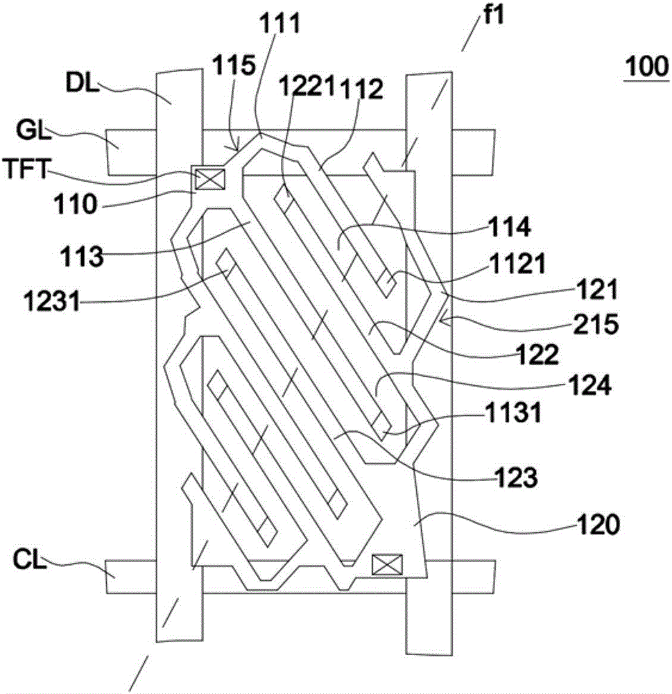
[0022] figure 1 It is a schematic diagram of the pixel structure of the display panel according to the first embodiment of the present invention.

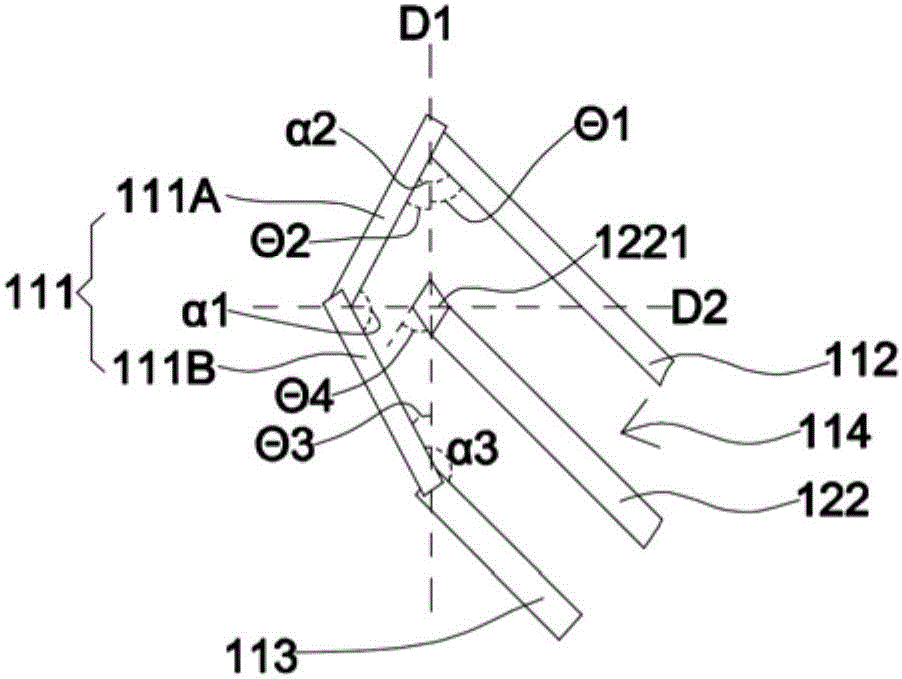
[0023] Such as figure 1 As shown, the display panel includes a first substrate, a second substrate and a liquid crystal layer opposite to each other. The liquid crystal layer is sealed between the first substrate and the second substrate (not shown), and a plurality of pi...


PUM


Abstract

The invention relates to a display panel. The display panel comprises a first substrate and a second substrate which are relative to each other, and a liquid crystal layer which is arranged on the middle of the first substrate and the second substrate. The display panel also consists of a plurality of pixel structures and a black matrix. The pixel structures, which are arranged on a first surface of the first substrate, include a first driving electrode which consists of a first junction, a plurality of first branch electrodes, and a plurality of first end electrodes. For each of the first branch electrodes, its electrical property of a first end is connected with the first junction, while the electrical property of a second end is connected with the first end electrode. The first end and the second end are relative to each other. The black matrix is positioned on a second surface of the second substrate. The second surface is relative to the first surface. The black matrix, in the thickness direction of the first substrate, is provided with vertical projection on the first surface. There are some overlaps between the fist junction and the vertical projection. The display panel disclosed by the invention is provided with high ray transmittance.

Description

technical field [0001] The invention belongs to the field of display technology, and relates to a liquid crystal display panel driven by a horizontal electric field. Background technique [0002] At present, the market is oriented toward high contrast ratio, no gray scale inversion, high brightness, and high color saturation for TFT liquid crystal display panels. , rapid response (response) and wide viewing angle (viewing angle) and other directions. Currently common wide viewing angle technologies include twisted nematic liquid crystal (TN) plus wide viewing film (wide viewing film), in-plane switching (In-Plane Switching, IPS) liquid crystal display panel, fringe field switching (Fringe Field Switching) , FFS) liquid crystal display panel and multi-domain vertical alignment (Multi-domain Vertical Alignment, MVA) liquid crystal display panel. [0003] In-Plane Switching (IPS) liquid crystal display panels generate a plane electric field between the electrodes of the pixel...

Claims


Application Information

Patent Timeline
Patent Type & Authority Applications(China)
IPC IPC(8): G02F1/1343G02F1/1335G02F1/137G02F1/1362
CPCG02F1/133512G02F1/134309G02F1/134363G02F1/136286G02F1/137G02F1/13793
Inventor 曹梓毅陈薏庭蔡正晔
Owner AU OPTRONICS CORP
Learn More