Synchronous rectifier used for power converter and operation method of synchronous rectifier

A technology of synchronous rectifier and power converter, which is applied in the conversion device of output power, the conversion of AC power input to DC power output, electrical components, etc., can solve the problem that the synchronous rectifier cannot generate the gate control signal, etc.

Active Publication Date: 2017-03-22
LEADTREND TECH
View PDF6 Cites 4 Cited by
  • Summary
  • Abstract
  • Description
  • Claims
  • Application Information

AI Technical Summary

Problems solved by technology

At this time, because when the AC / DC power converter is turned on and the power switch is turned on, the secondary side of the AC / DC power converter is used to drive the synchronous rectifier applied to the AC / DC power converter The driving voltage of the synchronous rectifier is not enough to drive the synchronous rectifier, so the synchronous rectifier cannot generate a gate control signal to turn off the metal-oxide-semiconductor transistor coupled to the secondary side of the AC / DC power converter, that is to say At this time, the gate of the metal oxide semiconductor transistor is in a floating state

Method used


Image

  • Synchronous rectifier used for power converter and operation method of synchronous rectifier
  • Synchronous rectifier used for power converter and operation method of synchronous rectifier
  • Synchronous rectifier used for power converter and operation method of synchronous rectifier

Examples


Embodiment Construction

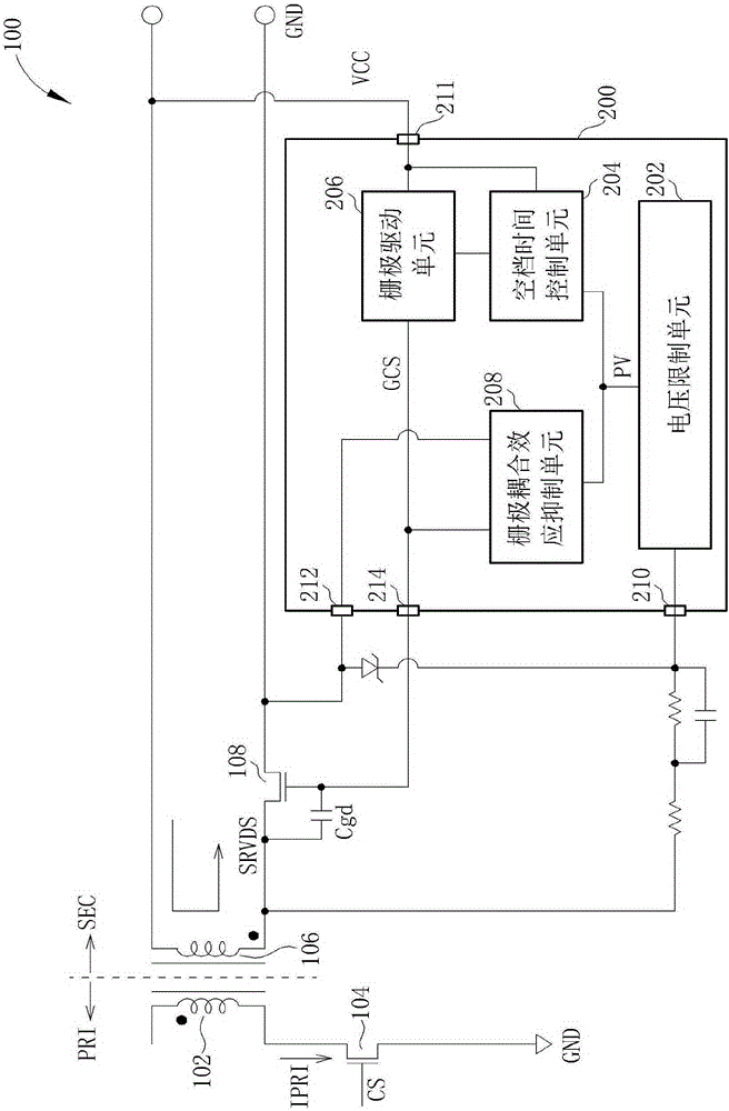
[0034] Please refer to figure 1 , figure 1 The first embodiment of the present invention discloses a schematic diagram of a synchronous rectifier 200 applied to a power converter 100, wherein the primary side PRI of the power converter 100 is only the primary side winding 102 and a power switch 104 shown in figure 1 , and the power converter 100 is an AC / DC power converter. like figure 1 As shown, the synchronous rectifier 200 includes a voltage limiting unit 202 , a dead time control unit 204 , a gate driving unit 206 and a gate coupling effect suppressing unit 208 . like figure 1 As shown, when the power converter 100 is turned on and the power switch 104 is turned on, the secondary winding 106 of the secondary side SEC of the power converter 100 will generate an induction according to the current IPRI flowing through the primary side PRI of the power converter 100 The voltage SRVDS (corresponding to the control signal CS of the power switch 104 ). like figure 1 As sho...


PUM


Abstract

The invention discloses a synchronous rectifier used for a power converter and an operation method of the synchronous rectifier. The synchronous rectifier comprises a gate coupling effect suppression unit, wherein the gate coupling effect suppression unit is used for suppressing induced voltage of a gate of a metal oxide semiconductor transistor coupled to a secondary side of the power converter to ensure that the metal oxide semiconductor transistor is closed when the power converter is started and a power switch at a primary side of the power converter is turned on, wherein drive voltage, for driving the synchronous rectifier, of the secondary side is not enough to drive the synchronous rectifier when the power converter is started, therefore, the condition that the metal oxide semiconductor transistor is closed can be ensured when the power converter is started and the power switch is turned on; the primary side and the secondary side can be prevented from being simultaneously conducted; and the condition that the power converter cannot be started or is broken can be avoided.

Description

technical field [0001] The invention relates to a synchronous rectifier applied to a power converter and an operation method thereof, in particular to a synchronous rectifier which can ensure that the primary side of the power converter and the secondary side of the power converter will not be turned on at the same time when the power converter is turned on Synchronous rectifier and method of operation thereof. Background technique [0002] When the AC / DC power converter is turned on and the power switch of the primary side of the AC / DC power converter is turned on, the secondary winding of the secondary side of the AC / DC power converter will The current on the primary side of the DC power converter produces an induced voltage. At this time, because when the AC / DC power converter is turned on and the power switch is turned on, the secondary side of the AC / DC power converter is used to drive the synchronous rectifier applied to the AC / DC power converter The driving voltage ...

Claims


Application Information

Patent Timeline
Patent Type & Authority Applications(China)
IPC IPC(8): H02M7/217
Inventor 林崇伟林扬盛
Owner LEADTREND TECH
Why Eureka
Try Eureka