Flue gas denitration reaction system

A reaction system and flue gas technology, applied in the field of flue gas denitrification reaction system, can solve the problems of complex and changeable flow field, concentration deviation, large denitration flue gas volume, etc., so as to improve denitration efficiency, improve utilization efficiency, and improve economy. Effect

Pending Publication Date: 2017-03-29
STATE GRID HENAN ELECTRIC POWER ELECTRIC POWER SCI RES INST +2
View PDF9 Cites 5 Cited by
  • Summary
  • Abstract
  • Description
  • Claims
  • Application Information

AI Technical Summary

Problems solved by technology

However, for the above-mentioned first patent, when there are large differences in the concentration of nitrogen oxides and ammonia in each zone, although the ammonia-nitrogen molar ratio in each zone can be evenly distributed, the amount of ammonia can also be adjusted according to the actual situation in each zone. Demand injection, but the corresponding catalyst loading is fixed, when the partition NO x Concentration exceeds the NO of the denitrification catalyst x When the load is on, it will still affect the denitrification efficiency of the system; and for the second patent, only the second layer mixer is installed alone without effective control of the ammonia injection area itself, so when the flue gas reaches the catalyst layer, the NH 3 and NO x There is still a concentration deviation, which makes the denitrification reaction insufficient, and there is a possibility that the already relatively uniform flow field of the flue gas will be broken again after the flue gas passes through the second layer mixer
[0006] It can be seen that due to the large volume of denitrification flue gas, the complex and changeable flow field, the NO x Concentration fluctuates frequently, there is still room for improvement by adjusting the amount of ammonia injection in the upstream and improving the denitrification efficiency of the system by increasing the mixing degree of the flow field in the downstream

Method used


Image

  • Flue gas denitration reaction system
  • Flue gas denitration reaction system
  • Flue gas denitration reaction system

Examples


Embodiment 1

[0027] Baseline conditions: using honeycomb catalyst, NO in the flue gas to be treated x Concentration 550mg / m 3 , O 2 The content is 3.5%, the reaction temperature is 370°C, and the ammonia nitrogen ratio is 0.85.

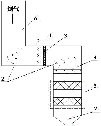
[0028] refer to figure 1 , a traditional flue gas denitrification reaction system, including an ammonia injection grid 1, a deflector 2, a static mixer 3, a rectification grid 4, and a catalyst layer 5, and the ammonia injection grid and the catalyst layer are sequentially arranged along the flow direction of the flue gas In the flue, the ammonia injection grid is connected to the inlet flue 6, the catalyst layer is connected to the outlet flue 7, the deflector is arranged at the corner of the flue, and the rectifying grill is arranged on the In the inlet section of the catalyst layer, the static mixer is arranged between the ammonia injection grid and the rectifying grid.

[0029] Both the inlet flue and the outlet flue are vertical flues; the ammonia injecti...

Embodiment 2

[0039] The reference conditions are the same as in Example 1.

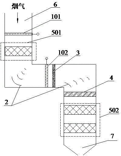
[0040] refer to figure 2 , the difference between the flue gas denitrification reaction system described in this embodiment and embodiment 2 is:

[0041] The ammonia injection amount of the first ammonia injection grid accounts for 30-50wt% of the total amount of ammonia injection under the reference conditions, and the remaining ammonia gas is injected into the flue through the second ammonia injection grid.

[0042] Test the denitrification efficiency of the system of the present invention reaches 90.8%, and the amount of ammonia escape is 1.8mg / m 3 .

Embodiment 3

[0044] The reference conditions are the same as in Example 1.

[0045] refer to figure 2 , the difference between the flue gas denitrification reaction system described in this embodiment and embodiment 2 is:

[0046] The catalyst loading in the catalyst pre-reaction zone accounts for 10-30 wt% of the total catalyst loading under the reference conditions, and the remaining catalyst is loaded in the catalyst main reaction zone.

[0047] It is measured that the denitrification efficiency of the system reaches 91.6%, and the ammonia escape amount is 1.7mg / m 3 .


PUM


Abstract

The invention provides a flue gas denitration reaction system, belonging to the technical field of flue gas denitration. The flue gas denitration reaction system comprises a first ammonia spraying grid, a catalyst pre-reaction area, a second ammonia spraying grid and a catalyst main reaction area, wherein the first ammonia spraying grid, the catalyst pre-reaction area, the second ammonia spraying grid and the catalyst main reaction area are arranged in a flue in sequence along a flue gas flowing direction, the first ammonia spraying grid is connected with an inlet flue, and the catalyst main reaction area is connected with an outlet flue. Under the condition of keeping certain catalyst content and ammonia content, by separately arranging the catalyst pre-reaction area and the catalyst main reaction area and correspondingly matching the first ammonia spraying grid and the second ammonia spraying grid, the denitration efficiency is improved; the amount of ammonia escape caused by insufficient denitration reaction and uneven flow field distribution is reduced, and meanwhile the economical efficiency of the system is improved.

Description

technical field [0001] The invention belongs to the technical field of flue gas denitrification, and in particular relates to a flue gas denitrification reaction system. Background technique [0002] At present, SCR denitrification technology is widely used in flue gas denitrification technologies at home and abroad due to its mature technology. With the improvement of environmental protection standards, the requirements for flue gas denitrification efficiency are becoming more and more stringent. In addition to the optimization of the catalyst itself, another key factor in improving the denitrification efficiency of SCR is the mixing and reaction of ammonia and flue gas. At present, the SCR denitrification system needs to be based on the flue gas NO x The concentration and flow velocity distribution are used to adjust the amount of ammonia sprayed in each area of ​​the ammonia injection grid to ensure the required denitrification rate. However, due to the large amount of...

Claims


Application Information

Patent Timeline
IPC IPC(8): B01D53/90B01D53/88B01D53/56
CPCB01D53/8631B01D53/88B01D53/90B01D2251/2062B01D2255/9032B01D2258/0283
Inventor 李敏王贺岑刘静宇詹胜平冯岩李玲刘综绪杜学森赵鑫平孟晓超程佳
Owner STATE GRID HENAN ELECTRIC POWER ELECTRIC POWER SCI RES INST
Why Eureka
Try Eureka