Solid-liquid four-phase horizontal spiral centrifuge

A decanter centrifuge and distance technology, applied in centrifuges, centrifuges with rotating drums, etc., can solve the problems of increasing production costs and inconvenient operation, saving production and use costs, convenient operation, and improving products. The effect of quality and productivity

Inactive Publication Date: 2017-03-29
JINAN HANRUIMI MECHANICAL EQUIP MFG CO LTD
View PDF9 Cites 4 Cited by
  • Summary
  • Abstract
  • Description
  • Claims
  • Application Information

AI Technical Summary

Problems solved by technology

This is not only inconvenient to operate but also increases production costs

Method used


Image

  • Solid-liquid four-phase horizontal spiral centrifuge
  • Solid-liquid four-phase horizontal spiral centrifuge
  • Solid-liquid four-phase horizontal spiral centrifuge

Examples


Embodiment 1

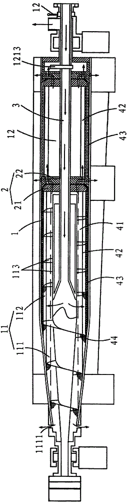
[0027] A solid-liquid four-phase decanter centrifuge includes a drum and a separation plate.

[0028] The drum 1 includes a first separation chamber 11 and a second separation chamber 12 , the first separation chamber 11 includes a conical section 111 and a straight section 112 , and the end of the conical section 111 has a slag outlet 1111 . A screw conveyor 113 is provided inside the first separation chamber 11 . The end of the second separation chamber 12 is fixedly connected to the end cover 121, and the end cover 121 is provided with liquid outlet holes 122 at different distances from the axis along the radial direction.

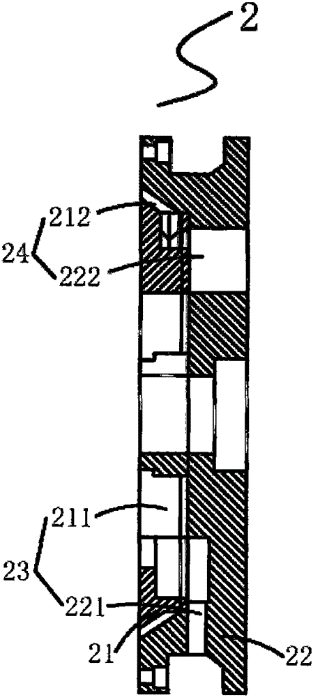
[0029] The separation plate 2 is arranged between the first separation chamber 11 and the second separation chamber 12 and sleeved on the feed pipe 3 . The separation plate 2 includes a gland 21 and a connecting plate 22 fixed on the gland 21 . The gland 21 is located in the first separation chamber 11 , and it is provided with 6 outer through holes 2...

Embodiment 2

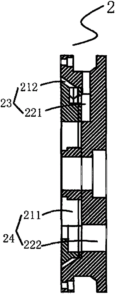
[0040] In this embodiment, the separation plate 2 is designed such that the communication hole 24 is close to the axis, and the overflow hole 23 is far away from the axis. That is to say, the gland 21 is located in the first separation chamber 11, and it is provided with 6 outer through-holes 211 near the axial center along the radial direction, and 6 inner through-holes 212 are arranged away from the axial center.

[0041] The outer through hole 221 of the connecting plate 22 is designed to be away from the axis, and the inner through hole 222 is close to the axis. The left end of the outer through hole 221 is connected with the inner through hole 212 on the gland 21 and the right end communicates with the inner wall of the drum 1, and the inner through hole 212 and the outer through hole 221 are connected to connect the first separation chamber 11 and the outer wall of the drum 1 Connected overflow hole 23. Compared with the first embodiment, the diameter of the inner through...


PUM


Abstract

The invention discloses a solid-liquid four-phase horizontal spiral centrifuge, which belongs to the field of centrifugal separation equipment. The solid-liquid four-phase horizontal spiral centrifuge comprises a rotary drum, wherein the rotary drum comprises a first separation chamber, a second separation chamber and a separation plate, the first separation chamber comprises a conic section and a straight section, a spiral conveyor is arranged in the first separation chamber, an end cover is fixedly connected to the end of the second separation chamber, and liquid holes at different distances from the axis are radially formed in the end cover; the separation plate is arranged between the first separation chamber and the second separation chamber, an overflowing hole which is used for communicating the first separation chamber with the outer wall of the rotary drum and a communicating hole which is used for communicating the first separation chamber with the second separation chamber are formed in the separation plate, and the distances between one end, which is located in the first separation chamber, of the overflowing hole and the axis as well as between one end, which is located in the first separation chamber, of the communicating hole and the axis are different; and the end cover comprises the separation plate and an outer cover which is fixedly connected to the separation plate, and a cavity is formed between the separation plate and the outer cover. Compared with the prior art, the solid-liquid four-phase horizontal spiral centrifuge has the beneficial effects that solid-liquid-liquid-liquid four-phase separation is realized, the separation diversity is increased, the product quality and the production efficiency are increased, and the cost is reduced.

Description

technical field [0001] The invention relates to the field of centrifugal separation equipment, in particular to a solid-liquid four-phase decanter centrifuge. Background technique [0002] The decanter centrifuge is a horizontal spiral unloading and continuous operation settling equipment, which can replace a lot of labor, reduce the factory area and improve production efficiency. Widely used in sewage clarification, biopharmaceutical separation, fruit juice fiber filtration, synthetic resin and other industries. [0003] The decanter centrifuges currently on the domestic market include two-phase and three-phase separation. The structure of the three-phase centrifuge is mainly composed of a differential, a screw conveyor, a drum, a casing, a machine base, a lubrication system, and a motor. Its working principle is: the separated material enters the drum through the feeding pipe and the screw outlet. Due to the different specific gravity, the centrifugal force is different...

Claims


Application Information

Patent Timeline
Patent Type & Authority Applications(China)
IPC IPC(8): B04B1/20B04B1/04B04B7/12B04B15/00
Inventor 田庆宝
Owner JINAN HANRUIMI MECHANICAL EQUIP MFG CO LTD
Why Eureka
Try Eureka