Alignment method for wireless charging coil, device and system

A wireless charging and coil technology, applied in battery/fuel cell control devices, charging stations, electric vehicle charging technology, etc., can solve the problems of slow alignment process and low efficiency, and achieve improved speed and accuracy, fast speed, The effect of high charging efficiency

Active Publication Date: 2017-03-29
SHENZHEN WOER HEAT SHRINKABLE MATERIAL +2
View PDF5 Cites 11 Cited by
  • Summary
  • Abstract
  • Description
  • Claims
  • Application Information

AI Technical Summary

Problems solved by technology

[0003] The existing alignment method is generally that the driver controls the electric vehicle to locate and align the wireless charging transmitting coil according to the positioning marks of the charging station, which requires the driver's manual control to realize the alignment of the wireless charging transmitting coil and the wireless charging receiving coil. One alignment process is slow and at the same time inefficient

Method used


Image

  • Alignment method for wireless charging coil, device and system
  • Alignment method for wireless charging coil, device and system
  • Alignment method for wireless charging coil, device and system

Examples


Embodiment 2

[0103] Embodiment 2. The difference between this embodiment and Embodiment 1 is that this embodiment only needs to obtain the current of the coil 20 at the power supply end, and its control process is simpler.

[0104] According to the existing theory, the charging circuit model of the charging system can be simplified as Figure 10 shown in the circuit diagram. The coupling tightness M between the coil 20 at the power supply end and the coil 40 at the vehicle end can be expressed as Where L1 and L2 are the self-inductance coefficients of the power supply coil 20 and the charging coil respectively, and k is the coupling coefficient.

[0105] Power supply coil 20 current i S and vehicle side coil 40 current i L The expression can be expressed as

[0106] where V L is the battery voltage, V S is the supply voltage,

[0107] Therefore it can be seen that when the battery charging property V L and I L When it remains unchanged, the larger the value of M is, the smaller...

Embodiment 3

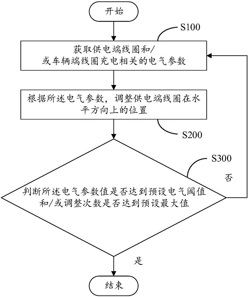
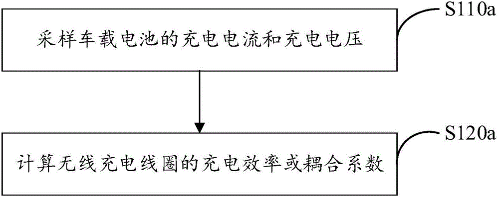
[0128] Embodiment three, refer to Figure 7 Specifically, the step "obtaining electrical parameters related to the charging of the coil 20 at the power supply end and / or the coil 40 at the vehicle end" includes:

[0129] Sampling the charging current and charging voltage of the vehicle battery, calculating the charging efficiency or coupling coefficient of the wireless charging coil; and obtaining the charging current of the coil 20 at the power supply end.

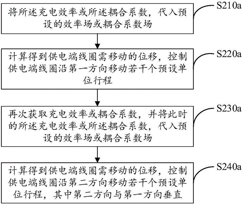
[0130] Specifically, the step "according to the electrical parameters, adjust the position of the power supply end coil 20 in the horizontal direction according to the preset unit stroke" specifically includes:

[0131] S210c. Substituting at least any two of the charging efficiency, the coupling coefficient, and the charging current into a corresponding preset efficiency field, coupling coefficient field, or current field, respectively;

[0132] S2210c. Calculate and obtain the average displacement that the power supply...


PUM


Abstract

The invention discloses an alignment method for a wireless charging coil, a device and a system. The alignment method for the wireless charging coil comprises the following steps: acquiring charging-related electrical parameters of a power supply end coil and/or a vehicle end coil; adjusting the position of the power supply end coil in a horizontal direction according to the electrical parameters; judging whether an electrical parameter value reaches a preset electrical threshold and/or adjustment times reach a preset maximum value or not; and if so, finishing the alignment of the charging coil, and otherwise, circulating the steps. According to the technical scheme, the alignment speed of the wireless charging coil is improved, and the charging efficiency is improved.

Description

technical field [0001] The present invention relates to the technical field of wireless charging, in particular to a wireless charging coil alignment method, device and system. Background technique [0002] When an existing electric vehicle using wireless charging enters a wireless charging station for charging, it is necessary to align the wireless charging receiving coil at the bottom of the vehicle with the wireless charging transmitting coil on the ground to ensure the maximum charging efficiency. [0003] The existing alignment method is generally that the driver controls the electric vehicle to locate and align the wireless charging transmitting coil according to the positioning marks of the charging station, which requires the driver's manual control to realize the alignment of the wireless charging transmitting coil and the wireless charging receiving coil. An alignment process is slow and at the same time inefficient. Contents of the invention [0004] The main p...

Claims


Application Information

Patent Timeline
Patent Type & Authority Applications(China)
IPC IPC(8): B60L11/18
CPCB60L53/38B60L58/10Y02T10/70Y02T10/7072Y02T90/12Y02T90/14
Inventor 周诚智
Owner SHENZHEN WOER HEAT SHRINKABLE MATERIAL
Why Eureka
Try Eureka