Phase-locked loop circuit, date recovery circuit, and control method of phase-locked loop circuit

A phase-locked loop and current control technology, which is used in the control of data recovery circuits and phase-locked loop circuits, and the field of phase-locked loop circuits, which can solve the problem of long locking time, slow response speed, large time constant, etc. question

Active Publication Date: 2017-03-29
HUAWEI TECH CO LTD
View PDF5 Cites 5 Cited by
  • Summary
  • Abstract
  • Description
  • Claims
  • Application Information

AI Technical Summary

Problems solved by technology

Since the circuit composed of resistor R1 and capacitor C1 in the first filter unit has a large

Method used


Image

  • Phase-locked loop circuit, date recovery circuit, and control method of phase-locked loop circuit
  • Phase-locked loop circuit, date recovery circuit, and control method of phase-locked loop circuit
  • Phase-locked loop circuit, date recovery circuit, and control method of phase-locked loop circuit

Examples


Embodiment Construction

[0073] The following will clearly and completely describe the technical solutions in the embodiments of the present invention with reference to the accompanying drawings in the embodiments of the present invention. Obviously, the described embodiments are only some, not all, embodiments of the present invention. Based on the embodiments of the present invention, all other embodiments obtained by persons of ordinary skill in the art without making creative efforts belong to the protection scope of the present invention.

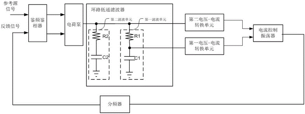
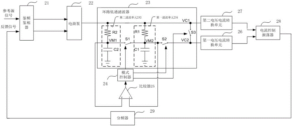
[0074] figure 2 A schematic structural diagram of a phase-locked loop circuit provided by an embodiment of the present invention is described, and the phase-locked loop circuit includes:

[0075] Phase Frequency Detector (Phase Frequency Detector, PFD) 21 is used for receiving the reference source signal and the feedback signal output by the frequency divider, and generating a first error signal, wherein the first error signal includes the reference source si...


PUM


Abstract

The invention provides a phase-locked loop circuit which comprises a frequency and phase detector, a charge pump, a loop low-pass filter, a first voltage-to-current conversion unit, a second voltage-to-current conversion unit, a current controlled oscillator, a frequency divider, a comparator, and a mode controller. The loop low-pass filter includes a switch S1, a switch S2, and a switch S3. The mode controller is used for controlling on-off of the switch S1, the switch S2 and the switch S3. According to the phase-locked loop circuit, the rise speed of a second control voltage signal VC2 supplied to the first voltage-to-current conversion unit can be improved, so that the second control voltage signal VC2 can reach the voltage value of a first control voltage signal VC1 supplied to the second voltage-to-current conversion unit in a short period of time, the establishment speed of the phase-locked loop circuit is improved, and the phase-locked loop circuit can make a response quickly.

Description

technical field [0001] The invention relates to a phase-locked loop circuit, in particular to a phase-locked loop circuit, a data recovery circuit and a control method for the phase-locked loop circuit. Background technique [0002] figure 1 A schematic structural diagram of a dual-loop phase-locked loop circuit is described. The dual-loop phase-locked loop circuit includes a frequency detector, a charge pump, a loop low-pass filter, a first voltage-current conversion unit, and a second voltage-current conversion unit. unit, a current-controlled oscillator and a frequency divider, wherein the loop low-pass filter includes a first filter unit and a second filter unit, and the circuit composed of a resistor R1 and a capacitor C1 in the first filter unit has a relatively large time constant , and is much larger than the time constant of the circuit composed of resistor R2 and capacitor C2 in the second filter unit, the first voltage-current conversion unit has a larger voltage...

Claims


Application Information

Patent Timeline
IPC IPC(8): H03L7/085H03L7/18
CPCH03L7/1075H03L7/101H03L7/087H03L2207/06H03L7/0807H03L7/099H03L7/093H03L7/0891H04L7/0331
Inventor 张兵照刘永旺
Owner HUAWEI TECH CO LTD
Why Eureka
Try Eureka