Eureka AIR delivers breakthrough ideas for toughest innovation challenges, trusted by R&D personnel around the world.

Touch panel, touch display device and display device

A touch panel and touch display technology, used in instruments, electrical digital data processing, electronic equipment, etc., can solve problems such as easy breakage, human injury, glass splash, etc., to reduce splinter splash, reduce damage, and improve anti-fall The effect of drop strength

Pending Publication Date: 2017-04-05
TPK TOUCH SOLUTIONS (XIAMEN) INC
View PDF6 Cites 11 Cited by
  • Summary
  • Abstract
  • Description
  • Claims
  • Application Information

AI Technical Summary

Problems solved by technology

However, this type of touch device is often easily broken when dropped due to insufficient strength, especially because the optical glue does not completely cover the edge of the touch panel, making the edge of the touch panel that is not glued by the optical glue more fragile. When falling, it is easy to cause glass to splash and cause harm to the human body
[0003] The aforementioned phenomenon of cracking of the touch device and splashing of glass due to insufficient strength also occurs in the structure of the touch panel and the display device

Method used

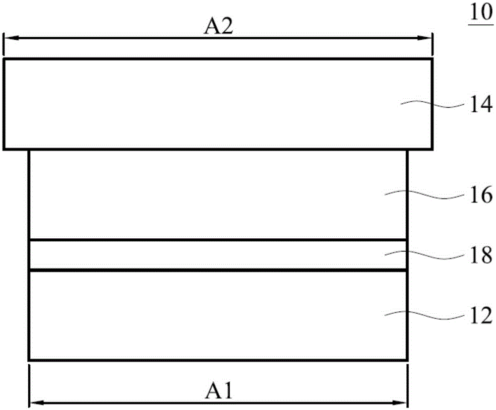
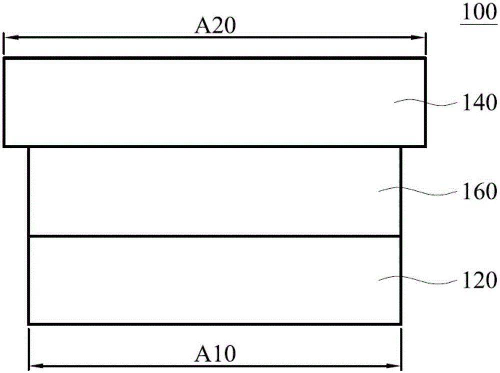
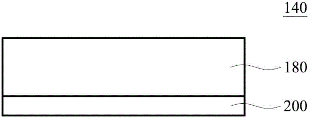

Image

  • Touch panel, touch display device and display device
  • Touch panel, touch display device and display device
  • Touch panel, touch display device and display device

Examples


Embodiment 1

[0052] In the following, the touch display device of the present invention is compared with the drop test of the traditional touch display device. In order to ensure the reliability of the test results, the traditional touch display device uses ordinary optical glue, while the touch display device of the present invention uses this The optical glue of the invention has the same structure as other components. Among them, sample 1 and sample 2 are touch display devices of the present invention, and sample 3 and sample 4 are traditional touch display devices.

[0053] Table 2

[0054] Ball height sample 1 sample 2 sample 3 Sample 4 30cm unbroken unbroken unbroken unbroken 50cm unbroken unbroken rupture rupture 100cm unbroken unbroken rupture rupture

[0055] The test results in Table 2 show that when the height of the falling ball is 30cm, neither the traditional touch display device nor the touch display device of the...

Embodiment 2

[0057] A comparison of the drop test of the traditional touch display device and the touch display device of the present invention, wherein the structure of the traditional touch display device is: a single-chip touch panel, a hard coating film, a traditional optical glue, and a liquid crystal display module stacked in sequence Plus, the touch display device of the present invention uses figure 2 The touch display device 100 corresponding to the embodiment is a test sample, wherein the touch panel is image 3 The single-chip touch panel 140 of the embodiment is taken as an example. The traditional touch display device (sample 4, sample 5) and the touch display device of the present invention (sample 1, sample 2, sample 3) were dropped and dropped with different steel ball weights (100g, 130g, 150g) respectively (ball height :100cm). The test results are shown in Table 3 below.

[0058] table 3

[0059]

[0060]According to the results in Table 3, when a steel ball with...


PUM


Abstract

The present invention provides a touch panel. The touch panel comprises: a substrate; a cover plate provided on the substrate; an optical glue disposed between the substrate and the cover plate, wherein an elastic modulus of the optical glue is between 1x10<7> Pa and 1x10<10> Pa; and a touch sensing layer disposed an upper surface or a low surface of the substrate or the upper surface and the low surface of the substrate. The present invention further provides a touch display device and a display device. The present invention further provides a touch display device and a display device, which both comprise an optical glue with a relatively great elastic modulus. Therefore, anti-drop strength of products can be effectively improved, the rupture of the edge of the cover plate or the touch panel is reduced so that the splinters are not easy to spread, and damage to the human body is reduced.

Description

technical field [0001] The invention relates to the technical field of touch display, in particular to a touch panel with high strength and good explosion-proof performance, a touch display device and a display device. Background technique [0002] For the current touch device, in order to facilitate subsequent assembly, the size of the touch panel (TP for short) is generally slightly larger than that of the liquid crystal display module (LCM for short). The two are usually bonded with optical clear adhesive (OCA for short). However, this type of touch device is often easily broken when dropped due to insufficient strength, especially because the optical glue does not completely cover the edge of the touch panel, making the edge of the touch panel that is not glued by the optical glue more fragile. When falling, it is easy to cause glass to splash and cause harm to the human body. [0003] The aforementioned phenomenon of cracking of the touch device and splashing of glass...

Claims


Application Information

Patent Timeline
Patent Type & Authority Applications(China)
IPC IPC(8): G06F3/041
CPCB32B2307/412B32B7/12B32B2457/208B32B2307/54B32B17/06G06F3/044
Inventor 李裕文刘仁昌林瑞珍庄江强连虹艳
Owner TPK TOUCH SOLUTIONS (XIAMEN) INC
Why Eureka
Eureka Blog
Learn More