Supercharge Your Innovation With Domain-Expert AI Agents!

A dust removal module and a gas dust removal device

A gas dedusting and cabinet technology, applied in the direction of solid separation, electrostatic separation, chemical instruments and methods, etc., can solve the problems of ozone secondary pollution, high filtration resistance, etc., and achieve the effect of low purification cost, low energy consumption and simple structure

Active Publication Date: 2018-05-08
BEIJING NAIR TENG TECH CO LTD
View PDF8 Cites 0 Cited by
  • Summary
  • Abstract
  • Description
  • Claims
  • Application Information

AI Technical Summary

Problems solved by technology

[0004] Existing gas purification equipment has the problems of high filtration resistance, need to replace consumables, and easy to generate ozone to cause secondary pollution during use

Method used


Image

  • A dust removal module and a gas dust removal device

Examples


Embodiment 1

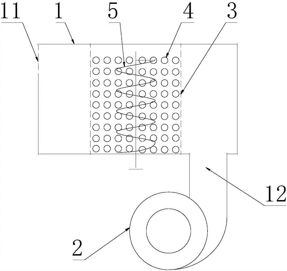
[0031] Such as figure 1 As shown, the present invention provides a dust removal module, which includes an outer cover 3 provided with several ventilation holes, the outer cover 3 is filled with several dust collection units 4, and the outer cover 3 is provided with a The agitator 5; there are at least two different electronegativity between the outer cover 3 and the dust collection unit 4, or the dust collection unit 4 and the agitator 5, or the dust collection unit 4.

[0032] There are at least two kinds of different electronegativity between some dust collection units 4, or dust collection unit 4 and agitator 5, or dust collection unit 4 and outer cover 3, that is to say, dust collection unit 4 and dust collection unit 4 have different electronegativity, dust suction unit 4 and outer cover 3 have different electronegativity, dust suction unit 4 and agitator 5 have different electronegativity, these three situations can exist independently, Any combination is also possible,...

Embodiment 2

[0046] The invention also discloses a gas dedusting device, such as figure 1 As shown, there is a dust removal module as described in Embodiment 1.

[0047] An air inlet 12 can be arranged on one side of the dust removal module, and the gas is guided from the air inlet 12 to pass through the dust removal module, and the purified gas is directly discharged through the vent hole on the outer cover 3 on the other side of the dust removal module. Of course, the air inlet 12 can also be changed to an air outlet 11, that is, only one air outlet 11 is provided, so that the gas passes through the dust removal module first, and then is discharged from the air outlet 11, or is led to a place where clean gas needs to be provided through a pipeline.

[0048] In addition to the above two structures, it is also possible to adopt figure 1 The structure shown: the gas dust removal device also includes: a cabinet 1 with an air inlet 12 and an air outlet 11, the dust removal module is arranged...


PUM


Abstract

The dust collecting device comprises a dust removing module and a gas dust-removing apparatus. The gas dust-removing apparatus comprises a cabinet with a gas inlet and a gas outlet, wherein the dust removing module is arranged in the cabinet, gas is discharged through the gas outlet after treatment with the dust removing module, the dust removing module comprises an outer shield provided with ventilation holes, and dust sucking units and stirrers are arranged in the outer shield. According to the present invention, the stirrers stir the dust sucking units to make the dust sucking units, the outer shield or the stirrers mutually collide and produce friction so as to form a high voltage electric field, and the dust in gas is adsorbed when the gas passes through the gap between the dust sucking units; the long-term electrification of the dust sucking unit can be ensured only requiring the continuous or non-continuous stirring of the stirrer, such that the dust in the gas can be adsorbed, and the energy source consumption is less; the dust removing module or dust sucking unit is not required to be replaced, such that the purification cost is low; and the high voltage electric field generated between the dust sucking unit or medium and the outer shield cannot generate the gas ionization phenomenon so as not to cause secondary pollution.

Description

technical field [0001] The invention relates to the technical field of gas purification equipment, in particular to a dust removal module and a gas dust removal device. Background technique [0002] At present, a large amount of dust is produced in various industrial processes, such as in factory workshops, combustion exhaust gas, etc.; in daily life, a large amount of exhaust gas, smog caused by mineral oil combustion, etc. These particulates are suspended in the gas and have a serious impact on human health, life and production. [0003] At present, the industrial dust removal methods mainly include electrostatic dust removal, filter bag dust removal and so on. The traditional electrostatic precipitator generates corona discharge through high voltage, ionizes the gas and charges the dust particles, and then is adsorbed to the electrode plate in the electric field to achieve the purpose of dust removal. In the process of corona discharge, the gas is ionized into positive ...

Claims


Application Information

Patent Timeline
Patent Type & Authority Patents(China)
IPC IPC(8): B03C3/28B03C3/34
CPCB03C3/28B03C3/34
Inventor 韩昌报王中林贺川高振亮
Owner BEIJING NAIR TENG TECH CO LTD
Features
  • R&D
  • Intellectual Property
  • Life Sciences
  • Materials
  • Tech Scout
  • Unparalleled Data Quality
  • Higher Quality Content
  • 60% Fewer Hallucinations
Learn More