
A rack of a multi-rotor unmanned aerial vehicle

A multi-rotor unmanned aerial vehicle and rack technology, which is applied to the fuselage frame, fuselage, aircraft parts, etc., can solve the problems of difficult to reproduce the product quality, difficult to maintain, and complicated to assemble, and achieves high reliability and easy disassembly. The effect of installation and maintenance

Active Publication Date: 2020-03-27
丰翼科技(深圳)有限公司
View PDF7 Cites 0 Cited by
  • Summary
  • Abstract
  • Description
  • Claims
  • Application Information

AI Technical Summary

Problems solved by technology

[0003] At present, there are several structural modes for the frame of multi-rotor drones: one is the overall structure of injection molded parts, which is suitable for mass production and small and light-loaded drones; the other is composite material integral molding structure, which is generally made by hand. The production efficiency is slow, and the product quality is difficult to reproduce, and the product reliability is difficult to control; the third is the plate-rod combination structure, with many parts, complex assembly, difficult maintenance, and low structural reliability

Method used


Image

  • A rack of a multi-rotor unmanned aerial vehicle
  • A rack of a multi-rotor unmanned aerial vehicle

Examples


Embodiment Construction

[0018] The application will be further described in detail below in conjunction with the accompanying drawings and embodiments. It should be understood that the specific embodiments described here are only used to explain related inventions, rather than to limit the invention. It should also be noted that, for ease of description, only parts related to the invention are shown in the drawings.

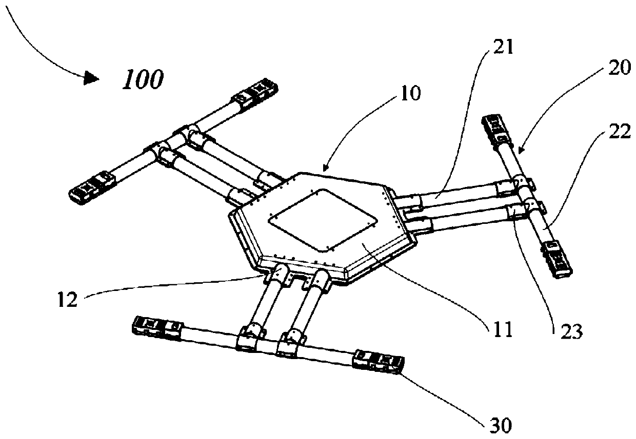
[0019] figure 1 It is a structural schematic diagram of a frame of a multi-rotor UAV according to an embodiment of the present invention. As shown in the figure, the frame 100 includes a center piece 10 , multiple sets of machine arms 20 and multiple pairs of motor mounts 30 .

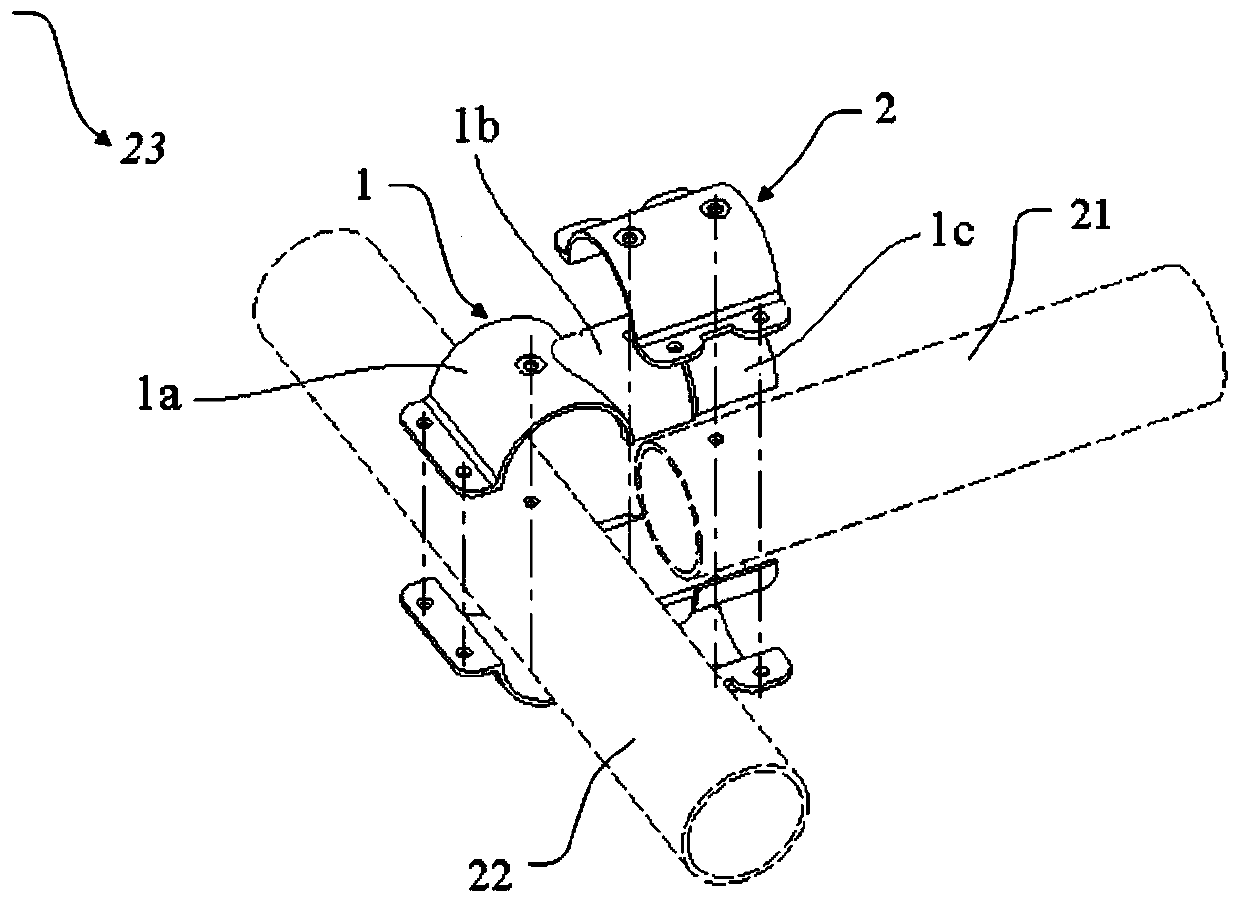
[0020] The central piece 10 includes a polygonal disk 11 and a plurality of pipe clamps 12 integrally formed with the polygonal disk 11, and the polygonal disk 11 includes a hollow cavity inside. The polygonal disk 11 can be set in a regular polygonal structure, or can be set in a non-regular polygonal struct...


PUM


Abstract

The invention discloses a rack of a multi-rotor-ring unmanned aerial vehicle. The rack comprises a center piece, a plurality of arm sets and a plurality of pairs of motor seats. The center piece comprises a polygonal disc and a plurality of pipe clamps integrally formed with the polygonal disc. The polygonal disc comprises an internally-hollow cavity. Each arm set comprises at least two first arms and a second arm connected to one ends of the at least two first arms, the first arms and the second arms are each of a pipe-shaped structure, and the other ends of the at least two first arms in each arm set are inserted into the corresponding pipe clamps. Each pair of motor seats is fixed to the two ends of the corresponding second arm correspondingly, and the motor seats are used for fixing a motor of the multi-rotor-ring unmanned aerial vehicle. According to the rack, the layout form of combining the center piece and the multiple arm sets is adopted, the structural size of the arms is reasonably set, the rack has the remarkable weight reduction effect while meeting the whole body vibration mode, and the rack is easy to demount, mount and maintain, high in reliability and suitable for batched production.

Description

technical field [0001] The invention relates to the technical field of unmanned aerial vehicles, in particular to a frame of a multi-rotor unmanned aerial vehicle. Background technique [0002] The multi-rotor UAV mainly includes multiple motors and propellers, flight control devices and load compartments, and is connected by a frame. Multi-rotor drones can be widely used in aerial fixed-point surveillance, monitoring, shooting, environmental monitoring, field investigation, case investigation, urban management, courtyard security, vehicle anti-theft, express delivery and other fields. [0003] At present, there are several structural modes for the frame of multi-rotor drones: one is the overall structure of injection molded parts, which is suitable for mass production and small and light-loaded drones; the other is composite material integral molding structure, which is generally made by hand. The production efficiency is slow, and the product quality is difficult to repro...

Claims


Application Information

Patent Timeline
Patent Type & Authority Patents(China)
IPC IPC(8): B64C1/06
CPCB64C1/061
Inventor 彭兴林赵磊柴峻彭国标
Owner 丰翼科技(深圳)有限公司
Learn More