On-line image visible ferrography reflected light imaging apparatus and method

An imaging device and imaging method technology, applied in image enhancement, image analysis, measurement device and other directions, can solve the problems of interfering abrasive grain imaging, blurred abrasive grain imaging, low image contrast between abrasive grain and background, etc., to improve reliability. effect of sex, elimination of influence, reduction of volume

Active Publication Date: 2017-04-19
XI AN JIAOTONG UNIV
View PDF8 Cites 9 Cited by
  • Summary
  • Abstract
  • Description
  • Claims
  • Application Information

AI Technical Summary

Problems solved by technology

[0004] However, in the patents 200610041773.X and 201410206588.6, the flow channels and online ferrography imaging devices are installed above the magnetic poles in sequence, and the transmitted and reflected light needs to pass through the oil layer to participate in the imaging. Bubbles and solid impurities in the oil interfere with the imaging of abrasive grains, affecting Image clarity and wear particle visual feature extraction. It is difficult for the ferrography imaging device involved in the non-oil discharge state to obtain a high-definition wear particle image, and the oil-impermeable deposited wear particles cannot be normally imaged.
The patents 201310141313.4 and 201610052551.1 adopt single reflected light illumination, and the depth of field of the imaging system is limited, and the image of moving abrasive particles in the oil is blurred. When the oil and abrasive particles are similar in color or the oil is opaque, the imaging device The wear particle image acquisition function will be lost, seriously affecting the accuracy and reliability of wear monitoring results
The patents 201510379282.5, 201520459761.3 and 201520460619.0 can theoretically eliminate the influence of oil and air bubbles on magnetic particle imaging, but there are structural problems. For example, the imaging module is installed in the V-shaped space above the two sets of excitation adsorption parts, and the two sets of excitation There is an included angle between the adsorption parts, and the distance between them is only 0.1 mm to 4 mm. Due to the limitation of the installation space and the working distance of the optical lens, the imaging module installed and fixed on the excitation adsorption part at a magnification of 10 to 1000 will cause structural interference. In addition, the imaging module in the device is vertically arranged with the iron core frame, and the imaging module is equipped with a prism, which cannot realize the miniaturization of the volume; in addition, the imaging module adopts a single reflection light source, and the grinding The image plane contrast between the grain and the background is low, which is not conducive to the acquisition of visual information of the grain

Method used


Image

  • On-line image visible ferrography reflected light imaging apparatus and method
  • On-line image visible ferrography reflected light imaging apparatus and method
  • On-line image visible ferrography reflected light imaging apparatus and method

Examples


Embodiment Construction

[0041] The structure and working principle of the present invention will be described in further detail below in conjunction with the accompanying drawings:

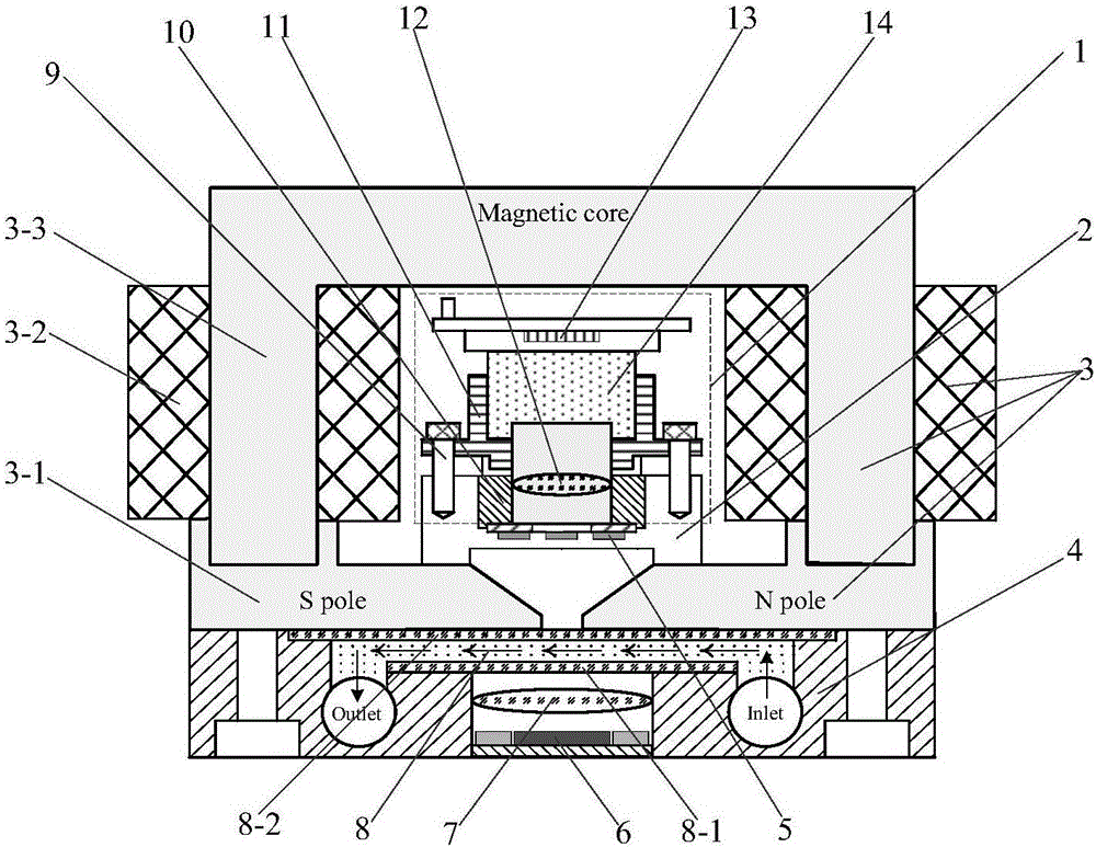
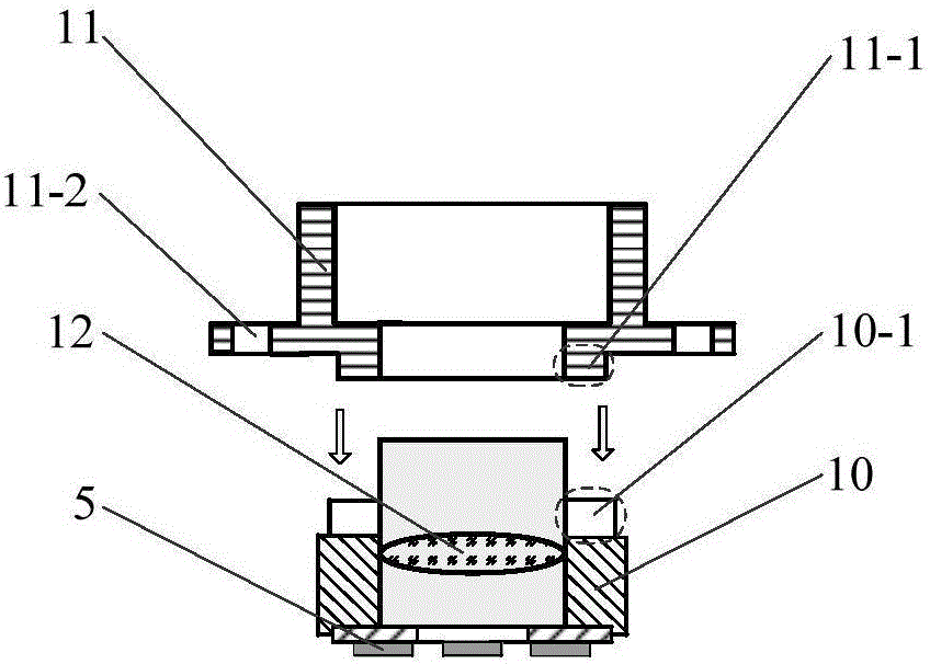
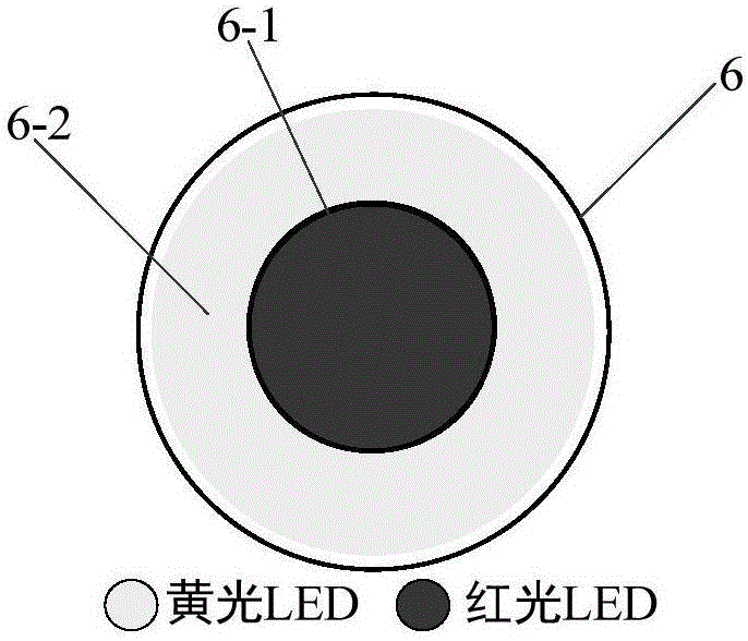
[0042] reference figure 1 , The online image visible ferrograph reflected light imaging device includes a focusing imaging mechanism 1, a connecting seat 2, a reflective light source 5 and a transmission light source 6. The imaging device of the present invention is assembled and fixed with the excitation module 3 and the flow channel 4 to form an online reflective light imaging Image visible ferrograph probe, in which the excitation module 3 is composed of a magnetic pole 3-1, an excitation coil 3-2 and an iron core 3-3. The flow channel 4 is fixed directly under the magnetic pole 3-1, focusing and imaging mechanism 1 and reflection The light source 5 is fixed on the side of the flow channel 4 close to the slide through the connecting seat 2 with screws, the transmission light source 6 is installed on the other side of the...


PUM

PropertyMeasurementUnit
transmittivityaaaaaaaaaa

Abstract

The invention discloses on-line image visible ferrography reflected light imaging apparatus and method. In the apparatus, a focusing and imaging mechanism and a reflective light source are fixed on one side, which is closed to a magnetic pole, of a flow channel, while a transmission light source is installed at the other side of the flow channel. The focusing and imaging mechanism and the reflective light source are arranged in an internal space of a magnetic excitation module, wherein the central optical axes thereof are coincided with the central axis of the magnetic excitation module. The apparatus has a compact structure and small size. The focusing and imaging mechanism and the reflective light source are fixed in a connection base, wherein the reflective light source is connected fixedly to the lower end of the focusing and imaging mechanism. A rectangular groove is formed in the bottom of the connection base for installing magnetic poles. The transmission light source is a double-color annular or planar light source. According to light transmittance of oil liquid, transmittance lights in different colors are supplied. Through adjustment on the light intensity of the transmission light source and the reflective light source, definition and image contrast ratio of abrasion particles are improved. Under non-oil-discharge status, the image of the abrasion particles of oil liquid in different light transmittances can be obtained reliably.

Description

Technical field [0001] The invention relates to an online monitoring microscopic imaging device and method for equipment wear particles, in particular to an online image visible ferrograph reflection light imaging device and method. Background technique [0002] The existing online ferrography technology can capture equipment wear information in real time without stopping the machine, judge the wear severity of the equipment friction pair based on the wear particle concentration and visual feature information, monitor and analyze the operation status and wear trend, and the wear data has high reliability , Which can guide condition-based maintenance and realize early failure prevention of equipment. [0003] In recent years, image-based online ferrograph wear particle monitoring technology has developed rapidly. For example, the patent "short deposition distance image type online ferrograph device and method (200610041773.X)" discloses a small-volume online image visible ferrograp...

Claims


Application Information

Patent Timeline
Patent Type & Authority Applications(China)
IPC IPC(8): G01N15/06
CPCG01N15/06G01N2015/0693G01N15/1031G01N15/147G01N2015/0053G01N33/2835G02B21/0016G02B21/025G02B21/06G02B21/365G01N21/85G01N21/8507G06T7/0004G06T2207/10152
Inventor 毛军红李博范斌郑东辉谢友柏
Owner XI AN JIAOTONG UNIV
Why Eureka
Try Eureka