
Iron chip recycling device for machine tool

A technology of recycling device and iron scraps, applied in metal processing machinery parts, maintenance and safety accessories, metal processing equipment, etc., can solve the problem of affecting production safety and production efficiency, debris easily flying into the operator's eyes, and inability to achieve cleaning production and other problems, to achieve the effect of clean production, elimination of potential safety hazards, and ease of movement

Inactive Publication Date: 2017-04-26
SHIYAN HANGAO ELECTRICAL & MECHANICAL TECH
View PDF0 Cites 8 Cited by
  • Summary
  • Abstract
  • Description
  • Claims
  • Application Information

AI Technical Summary

Problems solved by technology

[0002] At present, computer numerical control machine tools are famous for their high machining accuracy and high machining efficiency, but a lot of iron filings will be generated during the processing. For these iron filings, the traditional method is still used, that is, the iron filings continue to accumulate , the machine operator takes time out to clean in advance until after get off work; the machine operator uses a high-pressure air gun to blow the debris and dirt on the surface of the parts, causing the debris and dirt to fly around, causing pollution to the ground and the machine tool It is also a safety hazard, and debris is easy to fly into the eyes of the operator; therefore, the existing cleaning methods will seriously affect the sanitation inside the lathe and cannot achieve clean production. At the same time, iron filings will continue to accumulate, which will affect production safety and production efficiency. , the accumulation of iron filings greatly shortens the service life of the lathe

Method used


Image

  • Iron chip recycling device for machine tool
  • Iron chip recycling device for machine tool
  • Iron chip recycling device for machine tool

Examples


Embodiment Construction

[0015] The following will clearly and completely describe the technical solutions in the embodiments of the present invention with reference to the accompanying drawings in the embodiments of the present invention. Obviously, the described embodiments are only some, not all, embodiments of the present invention. Based on the embodiments of the present invention, all other embodiments obtained by persons of ordinary skill in the art without making creative efforts belong to the protection scope of the present invention.

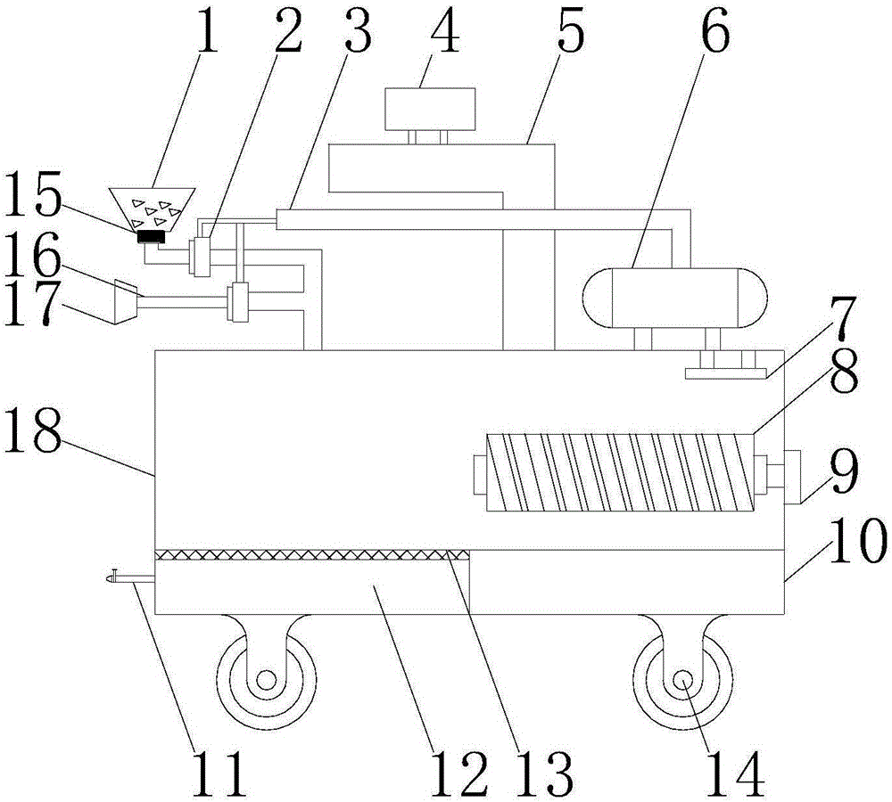
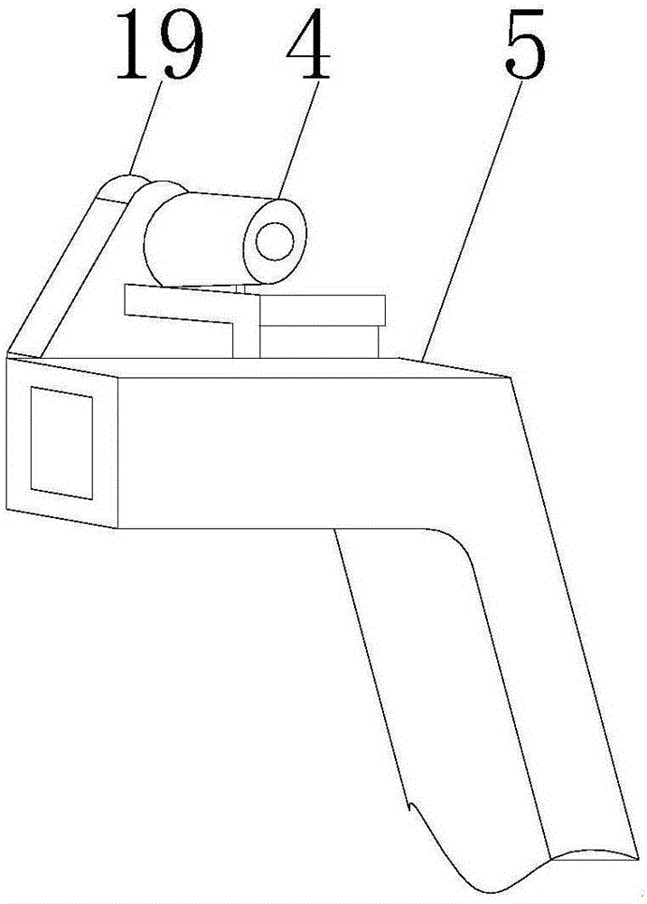
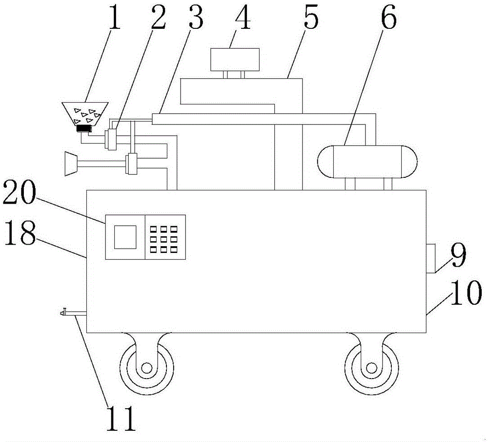
[0016] see Figure 1-4 , an embodiment provided by the present invention: a machine tool iron filings recovery device, including an electromagnetic collection bucket 1, a guide pipe 5, an air compressor 6, a manual suction nozzle 17 and a collection box 18, and the air compressor 6 is installed on On the collection box 18, and the air compressor 6 is connected with the electromagnetic collection bucket 1 and the manual suction nozzle 17 through the intake pipe...


PUM


Abstract

The invention discloses an iron chip recycling device for a machine tool. The iron chip recycling device comprises an electromagnetic collecting hopper, a flow guiding pipe, an air compressor, a manual suction nozzle and a collecting box. The air compressor is installed on the collecting box. The air compressor is connected with the electromagnetic collecting hopper and the manual suction nozzle through an air inlet pipe. The electromagnetic collecting hopper is connected with the manual suction nozzle and the collecting box through a conveying hose. The collecting box is connected with the flow guiding pipe provided with a water pump. A control panel is installed outside the collecting box. A cutting fluid storage box and an iron chip storage box are arranged in the collecting box. An electromagnetic rotating roller which is connected with a motor through a rotary shaft is arranged above the iron chip storage box. Universal wheels are installed outside the collecting box. The iron chip recycling device is simple in structure and convenient to operate, through cooperative application of the electromagnetic collecting hopper, the flow guiding pipe and the manual suction nozzle, the iron chip collecting efficiency is improved, clean production is achieved, and potential safety hazards are eliminated.

Description

technical field [0001] The invention relates to the technical field of iron filings recycling equipment, in particular to an iron filings recycling device for machine tools. Background technique [0002] At present, computer numerical control machine tools are famous for their high machining accuracy and high machining efficiency, but a lot of iron filings will be generated during the processing. For these iron filings, the traditional method is still used, that is, the iron filings continue to accumulate , until the machine tool operator takes time out to clean in advance; when cleaning the debris and dirt on the surface of the parts, the machine operator uses a high-pressure air gun to blow the debris and dirt around, causing pollution to the ground and the machine tool It is also a safety hazard, and debris is easy to fly into the eyes of the operator; therefore, the existing cleaning methods will seriously affect the sanitation inside the lathe and cannot achieve clean p...

Claims


Application Information

Patent Timeline
Patent Type & Authority Applications(China)
IPC IPC(8): B23Q11/00B23Q11/10
CPCB23Q11/0064B23Q11/1069
Inventor 赵华斌冯大庆王全侯自毅冯伶誉
Owner SHIYAN HANGAO ELECTRICAL & MECHANICAL TECH
Learn More