Cam type driving weft needle device

A cam type and weft needle technology, which is applied in the direction of textile, textile, papermaking, loom, etc., can solve the problems of large movement range, poor driving effect, and loose weaving, etc., and achieves compact cam structure, small inertial mass, and moment of inertia small effect

Inactive Publication Date: 2017-04-26
JAKOB MULLER CHINA CO LTD
View PDF7 Cites 0 Cited by
  • Summary
  • Abstract
  • Description
  • Claims
  • Application Information

AI Technical Summary

Problems solved by technology

At present, the common loom adopts the connecting rod transmission device, and the connecting rod drives the weft needle to reciprocate to realize the vertical and horizontal weaving of the weft and warp yarns, but the movement range is too large and the inertia is large, which will easily lead to loose weaving, and it is easy to break, and the driving effect is poor.
[0003] Its specific problems and shortcomings: (1) The deformation of the connecting rod itself (the object is not 100% rigid) will lead to the deviation of a series of parts after a long time; (2) The range of motion is large; (3) The deformation of the connecting rod itself The mass is large, so the inertia is large, it cannot be returned in time, it is easy to break, and it is not suitable for high-speed reciprocating motion

Method used


Image

  • Cam type driving weft needle device
  • Cam type driving weft needle device
  • Cam type driving weft needle device

Examples


Embodiment Construction

[0020] The present invention will be described in detail below with reference to the accompanying drawings and in combination with embodiments.

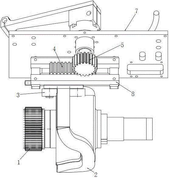
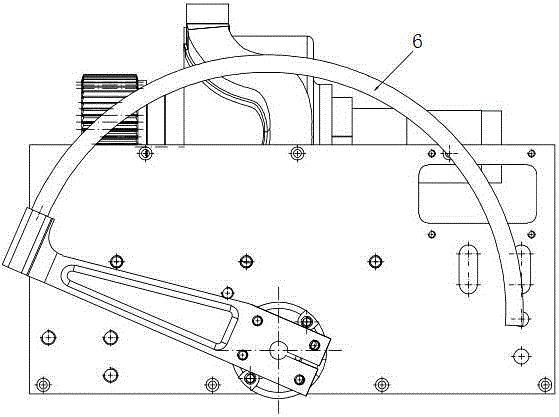
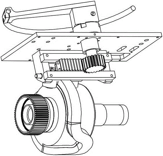
[0021] refer to Figure 1 to Figure 3 As shown, a cam-driven weft needle device includes a main shaft gear 1, a cam 2 coaxially arranged with the main shaft gear 1, and a rack support 3 matched with the working surface of the cam 2, and the tooth The bar support 3 is fixedly connected with a rack 4, the tooth surface of the rack 4 is provided with a countershaft gear 5 matched with it, the shaft of the countershaft gear 5 is provided with a weft needle 6, and the cam 2 is provided with It includes at least one curved portion 21 for pushing the rack support 3 to perform reciprocating linear motion.

[0022] The shaft of the countershaft gear 5 is arranged on a connecting cover 7 through corresponding bearings, and the weft needle 6 and the countershaft gear 5 are respectively arranged on both sides of the connecting cover 7 .

[002...


PUM


Abstract

The invention relates to a cam type driving weft needle device which comprises a spindle gear, a cam and a rack support, wherein the cam is coaxial with the spindle gear; the rack support is matched with a working surface of the cam; a rack is fixedly connected with the rack support; a countershaft gear matched with the rack is arranged on a toothed surface of the rack; a weft needle is arranged on a shaft of the countershaft gear; at least one section of a bent part for driving the rack support to have a reciprocal rectilinear motion is arranged on the cam. The combined structure of the cam and the gear transmission is utilized by the cam type driving weft needle device, so that the inertia mass is small, the self-rotation inertia is small, the device is more suitable for high-speed reciprocating motion, the reliability is high and the service life is long.

Description

technical field [0001] The invention relates to the technical field of looms, in particular to a cam type driving weft needle device. Background technique [0002] When the weft yarn and warp yarn are interwoven vertically and horizontally, an efficient and safe weft yarn feeding device is needed at this time. When the warp yarn is opened, the weft yarn just passes through, so as to ensure the continuity of weaving. At present, the common loom adopts a connecting rod transmission device, and the weft needle is driven by the connecting rod to reciprocate to realize the vertical and horizontal weaving of the weft and warp yarns. However, the large movement range and large inertia may easily lead to loose weaving, and are easy to break, and the driving effect is poor. [0003] Its specific problems and shortcomings: (1) The deformation of the connecting rod itself (the object is not 100% rigid) will lead to the deviation of a series of parts after a long time; (2) The range of ...

Claims


Application Information

Patent Timeline
Patent Type & Authority Applications(China)
IPC IPC(8): D03D47/27
CPCD03D47/275
Inventor 朱浩康刘风
Owner JAKOB MULLER CHINA CO LTD
Why Eureka
Try Eureka