Automotive oil economization control system

A control system and automobile technology, applied in the direction of electrical control, engine control, fuel injection control, etc., can solve problems such as inconvenient operation, and achieve the effects of reducing transportation costs, reducing fuel supply, and saving fuel consumption

Inactive Publication Date: 2017-04-26
潘云清
View PDF9 Cites 2 Cited by
  • Summary
  • Abstract
  • Description
  • Claims
  • Application Information

AI Technical Summary

Problems solved by technology

[0005] The purpose of the present invention is to address the above problems, to provide a simple structure, automatic operation, high reliability automotive fuel-saving control system; to solve the existing technical problems such as inconvenient operation in the prior art

Method used


Image

  • Automotive oil economization control system
  • Automotive oil economization control system
  • Automotive oil economization control system

Examples


Embodiment 1

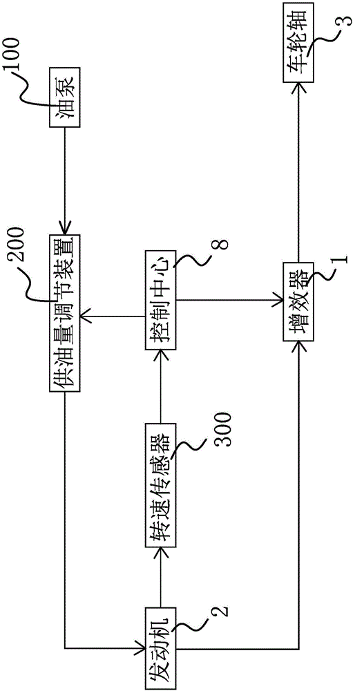
[0025] like figure 1 As shown, the automobile fuel-saving control system includes a control center 8, a multiplier 1, a fuel supply adjustment device 200 and a rotational speed sensor 300, wherein the multiplier 1 is arranged between the engine output shaft 21 and the wheel shaft 3 and is connected to the control The center 8 is connected, the oil supply adjustment device 200 is arranged on the oil circuit between the oil pump 100 and the engine 2 and connected with the control center 8 , and the rotational speed sensor 300 is arranged on the engine output shaft 21 and connected with the control center 8 .

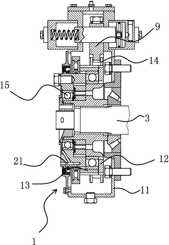
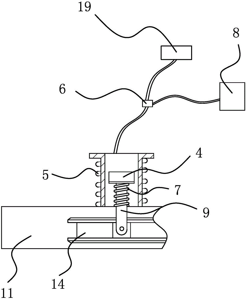
[0026] like figure 2 As shown, the multiplier 1 includes a casing 11 and a sliding sleeve 14 partially arranged in the casing 11. The sliding sleeve 14 is connected with a shift fork 9 capable of one-way clutching of the engine output shaft 21 and the wheel shaft 3. The fork 9 is connected with the control center 8 through an electric control device. A ratchet wheel 12 ...

Embodiment 2

[0031] like Figure 4 As shown, the content of embodiment 2 is basically the same as that of embodiment 1, the difference is that the shift fork 9 is connected with the control center 8 through the air control device, and the air control device includes an air pump 10, a cylinder 16, an air valve 17 and a return spring 7, The air pump 10 and the cylinder 16 are connected through an air circuit, and an air valve 17 is arranged on the air circuit between the air pump 10 and the cylinder 16 , and the control center 8 is connected with the air valve 17 . The cylinder 16 is located on the housing 11 and a piston 18 is housed in the cylinder 16 , and one end of the shift fork 9 is inserted in the cylinder 16 and can lean against the piston 18 . A return spring 7 located in the cylinder 16 is sheathed on the shift fork 9 , one end of the return spring 7 acts on the housing 11 , and the other end acts on the shift fork 9 . The opening and closing of the air valve 17 is controlled by ...


PUM


Abstract

The invention provides an automotive oil economization control system, belongs to the technical field of automatic control and solves the problem of inconvenient operation of the existing automotive oil economization control system. The automotive oil economization control system comprises a control center, an augmenter, an oil supply quantity adjusting device and a rotation speed sensor; the augmenter is arranged between an engine output shaft and a wheel shaft and is connected with the control center; the oil supply quantity adjusting device is arranged in an oil way between an oil pump and an engine and is connected to the control center; the rotation speed sensor is arranged on the engine output shaft and is connected to the control center; the control center is capable of controlling the augmenter to enable the engine output shaft to not drive the wheel shaft to rotate again when the rotation speed sensor detects that the rotation speed of the engine output shaft reaches the set value; meanwhile, the control center is capable of controlling the oil supply quantity adjusting device to reduce the oil supply quantity of the oil way or enable the oil way to be in cut-off state. The automotive oil economization control system has the advantages of simple structure, automatic operation and high reliability.

Description

technical field [0001] The invention relates to the field of automatic control, in particular to an electronic control system, in particular to an automobile fuel-saving control system. Background technique [0002] During the driving process of the car, there will be frequent speed changes, often accompanied by acceleration, deceleration and coasting motions. Sometimes the engine drives the vehicle, and sometimes the inertia of the car drives the engine in reverse. The above-mentioned changes cannot be grasped and controlled by the driver at any time, so the inertial energy in the driving process of the car is transmitted to the engine through the transmission shaft and is wasted in vain when it is dragged backwards, which results in the loss of inertial energy or fuel consumption during acceleration. increase, and at the same time increase the pollution of the exhaust gas to the environment during the driving of the car. [0003] In order to make full use of the inertial ...

Claims


Application Information

Patent Timeline
Patent Type & Authority Applications(China)
IPC IPC(8): F02D41/30F16D27/118F16D25/061F16D27/14B60W10/02B60W10/06B60W30/18
CPCF02D41/30B60W10/02B60W10/06B60W30/18072B60W2030/1809B60W2510/0647B60W2710/021B60W2710/0605F16D25/061F16D27/118F16D27/14
Inventor 潘云清
Owner 潘云清
Why Eureka
Try Eureka