Fatigue test hydraulic loading device for rigid material

A fatigue test and hydraulic loading technology, which is applied in fluid pressure actuation devices, analysis materials, measurement devices, etc., can solve problems such as low work efficiency and complex systems, and achieve high work reliability, low operating costs, and additional shock loads low effect

Active Publication Date: 2017-04-26
LIUZHOU VOCATIONAL & TECHN COLLEGE
View PDF6 Cites 6 Cited by
  • Summary
  • Abstract
  • Description
  • Claims
  • Application Information

AI Technical Summary

Problems solved by technology

However, using the existing hydraulic system and the hydraulic circuit controlled by the solenoid valve is not only complicated, but the solenoid valve is prone to failure during long-term repeated cycle work, which affects the reliability of the system. Work efficiency is also very low under small power pulsating cycle load

Method used


Image

  • Fatigue test hydraulic loading device for rigid material

Examples


Embodiment Construction

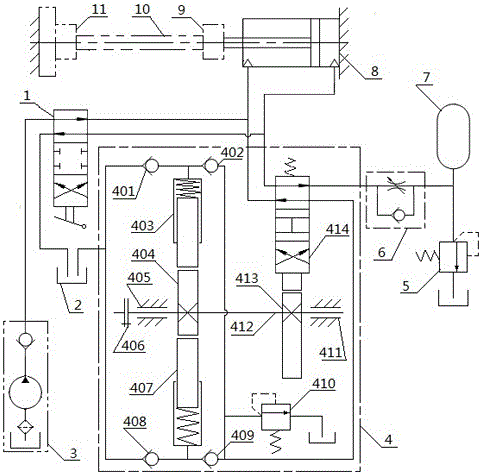
[0020] A hydraulic loading device for a rigid material fatigue test, including a clamping pump station 3, a loading pump station 4, a manual reversing valve 1, an oil cylinder 8, a specimen fixture, an accumulator 7 and an oil storage tank 2 ( figure 1 The middle oil storage tanks 2 are all the same oil storage tank 2, which are only drawn in different parts for the convenience of viewing), the test piece fixtures include fixtures I11 and fixtures II9, and the fixtures I11 are fixed on the machine base. The clamp II9 is ​​connected with the piston rod on the oil cylinder 8, and the cylinder body of the oil cylinder 8 is also fixed on the machine base. The loading pump station 4 includes plunger pump I 403, plunger pump II 407, eccentric wheel 404, cam 413 and reversing valve 414, and the described eccentric wheel 404 and cam 413 are respectively fixed on the same shaft connected to the motor. Above, the plunger pump I 403 and the plunger pump II 407 are respectively driven and...


PUM


Abstract

The invention relates to a fatigue test hydraulic loading device for a rigid material. The fatigue test hydraulic loading device for the rigid material comprises a clamping pump station, a loading pump station, a manual reversing valve, an oil cylinder, a test piece clamp and an oil storage tank, wherein a clamp I is fixedly arranged on a machine seat; a clamp II is connected with a piston rod on the oil cylinder; the clamping pump station is connected with an oil path of the oil cylinder through the manual reversing valve; an eccentric wheel and a cam are both fixedly arranged on the same shaft connected with a motor; a plunger pump I and a plunger pump II are in driving connection with the eccentric wheel; the reversing valve is in driving connection with the cam; the plunger pump I and the plunger pump II are connected with the oil path of the oil cylinder through a check valve and the reversing valve; and the plunger pump I and the plunger pump II are connected with an oil path of the oil storage tank through check valves. The cam coaxial with the loaded plunger pumps is used for controlling the reversing valve to carry out switching of the oil paths of the hydraulic system, pulling force and pressure can be applied to the tested material circularly, and therefore work reliability is quite high.

Description

technical field [0001] The invention relates to the technical field of engineering material testing, in particular to a hydraulic loading device for rigid material fatigue testing. Background technique [0002] In the field of engineering material testing technology, it is necessary to carry out fatigue tests such as tension and torsion on metal materials such as steel and their products, and it is necessary to apply "tension-compression" or "positive-reverse" direction torsion to the tested material. Cyclic load, and the application of this cyclic load lasts for a period of time and reaches a high number of cycles. It is an ideal technical solution to use a hydraulic system to realize this loading function. However, using the existing hydraulic system and the hydraulic circuit controlled by the solenoid valve is not only complicated in the system, but also the solenoid valve is prone to failure during long-term repeated cycle work, which affects the reliability of the syste...

Claims


Application Information

Patent Timeline
Patent Type & Authority Applications(China)
IPC IPC(8): F15B11/028F15B1/02G01N3/36
CPCF15B1/024F15B11/028F15B2211/20576F15B2211/50G01N3/36G01N2203/0005G01N2203/0048G01N2203/0073
Inventor 覃日强王大红周文海覃轶科陈超山
Owner LIUZHOU VOCATIONAL & TECHN COLLEGE
Why Eureka
Try Eureka