Special automatic test system used for microwave component power supply

A technology for microwave components and power supplies, applied in the field of automated testing of high-power microwave component power supplies, can solve the problems of low test data accuracy, low repetition efficiency, reading errors, etc., and achieve convenient data comparison and historical data query, Guaranteed Accuracy and Reliability, Guaranteed Reliability and Safety Effectiveness

Active Publication Date: 2017-04-26
BEIJING SATELLITE MFG FACTORY
View PDF8 Cites 2 Cited by
  • Summary
  • Abstract
  • Description
  • Claims
  • Application Information

AI Technical Summary

Problems solved by technology

[0004] The traditional high-power microwave component power supply electrical performance test is mainly completed by manual testing, through manual operation of various instruments and equipment, manual reading, recording, and analysis of test data, while high-power microwave component power supply electrical performance testing has many technical indicators, and the test equipment The operation is very cumbersome, there are a lot of repetitive and inefficient work, the amount of test data is also large, and the workload of manual recording is heavy. It takes at least 24 hours to test a product
In addition, relying on manual reading data will also produce some reading errors, and more accurate test data cannot be obtained, which will bring certain difficulties to subsequent test data analysis.
[0005] The traditional test method of high-power microwave component power supply is inefficient and the accuracy of test data is not high, which seriously delays the development and production progress of large-scale similar power supply products. Therefore, it is imperative to adopt advanced and efficient automated test technology, which can Effectively guarantee the progress of product development, check and confirm whether each performance index of the product meets the requirements of the mission statement

Method used


Image

  • Special automatic test system used for microwave component power supply

Examples


Embodiment Construction

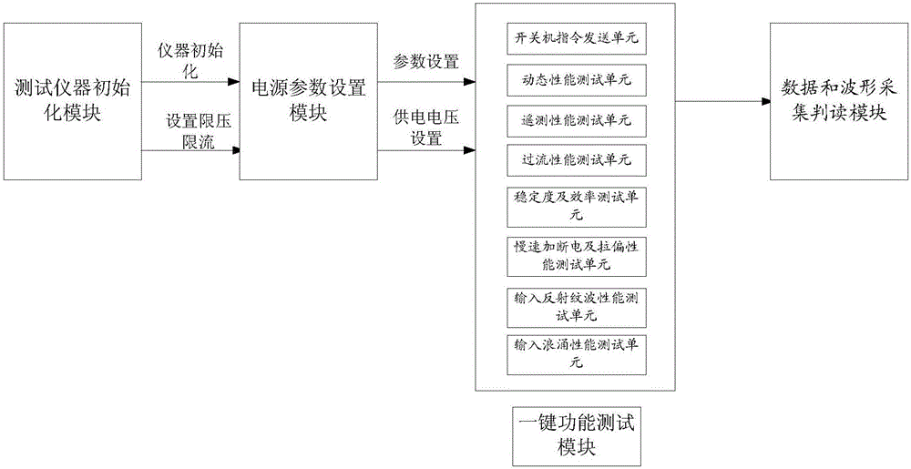
[0026] like figure 1 As shown, the present invention mainly includes a test instrument initialization module, a power parameter setting module, a one-key test function module, and a data and waveform acquisition and interpretation module.

[0027] When testing the microwave component power supply, the computer initializes each test instrument through the test instrument initialization module to ensure that each test instrument maintains a reliable and effective communication connection with the computer. And limit the maximum output voltage and maximum output current of the power supply to ensure that the subsequent power supply voltage is limited within the voltage range that the power supply of the microwave component to be tested can withstand, and prevent the output of the power supply from being treated due to programming errors and human errors. The power supply of the microwave component under test is not damaged, which ensures the reliability of the test.

[0028] Aft...


PUM


Abstract

Provided is a special automatic test system used for a microwave component power supply. The system mainly comprises a test apparatus initialization module, a power supply parameter setting module, a one-key test function module, and a data and waveform acquisition interpretation module. According to the test system, the test efficiency of the microwave component power supply can be improved by about 96%; automatic acquisition and storage of test data and waveforms can be realized, errors caused by artificial reading of the data can be avoided, and the accuracy and the reliability of the test data are guaranteed; automatic interpretation of the test data can be realized, the data which is not in accordance with the requirement is automatically screened from huge test data volume, and compared with artificial interpretation, the time is saved, and the efficiency is improved; and over-voltage protection and over-current protection of the power supply are set, and an abnormal condition early warning mechanism is established so that the damage to the product due to artificial operation errors is prevented, and the reliability and the security of the test system in a usage process are guaranteed.

Description

technical field [0001] The invention relates to a special automatic test system for microwave component power supply, which is mainly used for automatic test of high-power microwave component power supply. Background technique [0002] The high-power microwave component power supply belongs to the bottleneck project of final assembly. It is a "bottleneck" research project proposed to solve the microwave power supply efficiency of the first generation of detailed survey satellites and improve the sensitivity of the microwave antenna system. Through the research of this project, it is necessary to realize the antenna Localization of load-specific high-efficiency DC / DC power supplies. Its research goals: comprehensively break through the key technologies of high-efficiency DC / DC power supplies for high-power loads, realize engineered products with an efficiency ≥ 85%, break the embargo of foreign microwave component power supplies, and support the development of aerospace equip...

Claims


Application Information

Patent Timeline
Patent Type & Authority Applications(China)
IPC IPC(8): G01R31/40
CPCG01R31/40
Inventor 胡文婷李海波曹辰磊李燕荣娜娜
Owner BEIJING SATELLITE MFG FACTORY
Why Eureka
Try Eureka