Method and apparatus to calculate target position using imaging spectrometer

An imaging spectrometer and imaging position technology, applied in the direction of measuring devices, instruments, positioning, etc., can solve problems affecting the measurement accuracy of imaging spectrometers, measurement results errors, drift errors, etc., to improve system accuracy, improve measurement accuracy, and ensure calculation accuracy Effect

Active Publication Date: 2017-04-26
CHANGCHUN INST OF OPTICS FINE MECHANICS & PHYSICS CHINESE ACAD OF SCI
View PDF5 Cites 4 Cited by
  • Summary
  • Abstract
  • Description
  • Claims
  • Application Information

AI Technical Summary

Problems solved by technology

It can be seen from the table on the right that the effective spectra are very close to each other. If the error in the x direction is greater than 0.5 pixels (these errors are mainly the calculation of the target accuracy error during calibration, the correction error at the position of the non-calibration point, and the image caused by temperature drift Surface position drift error, position changes between comp...

Method used


Image

  • Method and apparatus to calculate target position using imaging spectrometer
  • Method and apparatus to calculate target position using imaging spectrometer
  • Method and apparatus to calculate target position using imaging spectrometer

Examples


Embodiment 1

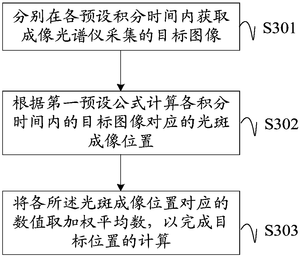
[0053] see first image 3 , image 3 A schematic flowchart of a method for calculating a target position by an imaging spectrometer provided in an embodiment of the present invention, the embodiment of the present invention may include the following contents:

[0054] S301: Acquire a target image collected by an imaging spectrometer within each preset integration time respectively.

[0055] The integration time may be preset, or may be set according to the needs of the technicians themselves during testing, which does not affect the implementation of the embodiments of the present invention.

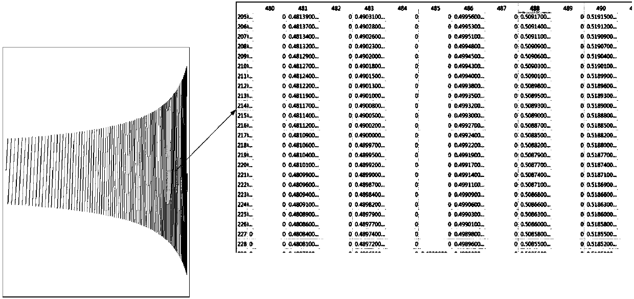
[0056] The integration time is short, the spot energy will not be saturated, and the gray value of the spot has a linear relationship with the spot energy. Without considering the noise, the position of the center of gravity of the spot is close to the center of the spot; however, the spot energy in the image is low, and the electronic noise is relatively serious, and the noise has a s...

Embodiment 2

[0071] see Figure 4 , Figure 4 A schematic flowchart of another method for calculating a target position by an imaging spectrometer provided in an embodiment of the present invention may specifically include the following content:

[0072] S401: Acquire a target image collected by an imaging spectrometer within each preset integration time respectively.

[0073] The specifics are the same as those described in S301 of the first embodiment, and are not repeated here.

[0074] S402: Acquire a preset number of sub-images collected by the imaging spectrometer in each of the integration times respectively.

[0075] S403: Select a sub-image from the sub-images corresponding to each integration time according to a preset method as a target image of the corresponding integration time.

[0076] Specifically, it can be:

[0077] Calculate the spot imaging position of each sub-image corresponding to each integration time according to the second preset formula;

[0078] Select a su...

Embodiment 3

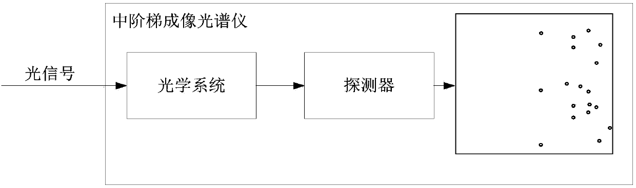
[0096] see Figure 5 , Figure 5 A structural diagram of an imaging spectrometer calculating target position device provided in an embodiment of the present invention in a specific implementation manner, the device may include:

[0097] An information acquisition module 501 is configured to acquire target images collected by the imaging spectrometer within each preset integration time respectively.

[0098] The calculation module 502 is configured to calculate the spot imaging position corresponding to the target image in each integration time according to the first preset formula; take a weighted average of the values ​​corresponding to each of the spot imaging positions to complete the calculation of the target position.

[0099] Optionally, in some implementations of this embodiment, the information acquiring module 501 may further include, for example:

[0100] an acquiring sub-image unit 5011, configured to acquire sub-images of a preset number of frames collected by th...


PUM


Abstract

The embodiments of the invention disclose a method and apparatus to calculate target position using an imaging spectrometer. The method comprises the following steps: calculating the corresponding light spot imaging positions through target images acquired by the imaging spectrometer within the preset various integration times; then calculating the weighted average number of the plurality of light spot imaging position values; and using the weighted average number as the final position value of the light spot imaging. According to the technical schemes of the invention, the weighted average number of the light spot imaging positions of a plurality of target images is used as the final target position, which effectively avoids the calculation errors caused from the fluctuation of the light spot positions, ensures the calculation precision of the target position, increases the positioning accuracy at some extent, raises the system precision of an imaging spectrometer and further increases the measurement accuracy of the imaging spectrometer. In addition, the embodiments of the invention also provide an apparatus to implement the method and so to make the method more practical and correspond to the apparatus.

Description

technical field [0001] The invention relates to the technical field of imaging spectrometer applications, in particular to a method and a device for calculating a target position by an imaging spectrometer. Background technique [0002] The traditional imaging system can only obtain the spatial image information of the target scene. The traditional spectrometer determines the material properties by obtaining the spectral information of the radiation intensity curve that changes with the wavelength, thereby obtaining the target spectral information. Imaging spectroscopy technology combines optical imaging technology with spectral detection technology to form a new remote sensing technology, which solves the problems of traditional optical imagers with images but no spectra and traditional spectrometers with spectra without images. [0003] Imaging spectrometer, also known as high spectral resolution remote sensing, its optical system consists of a front telephoto system and a...

Claims


Application Information

Patent Timeline
IPC IPC(8): G01S5/16G01J3/28
Inventor 王明佳尹禄张锐王宇庆朱继伟崔继承
Owner CHANGCHUN INST OF OPTICS FINE MECHANICS & PHYSICS CHINESE ACAD OF SCI
Why Eureka
Try Eureka