
Method and device for realizing low-power all-optical quantization based on micro-nano resonant cavity

A low-power, resonant cavity technology, applied in the field of low-power all-optical quantization, can solve the problems of complex structure, low power, and high sampling pulse power of optical analog signal all-optical quantization technology, and achieve high sampling pulse power and high precision Full light quantization, the effect of reducing requirements

Inactive Publication Date: 2017-04-26
TAIYUAN UNIV OF TECH
View PDF6 Cites 4 Cited by
  • Summary
  • Abstract
  • Description
  • Claims
  • Application Information

AI Technical Summary

Problems solved by technology

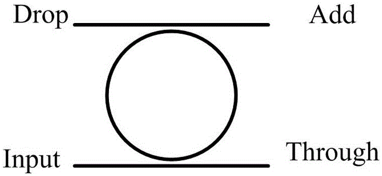
[0007] In order to solve the problems of complex structure and high sampling pulse power in the current all-optical quantization technology of optical analog signals, the present invention uses the characteristics of high nonlinearity and high quality factor of silicon-based micro-ring resonators to combine the existing all-optical sampling technology and Combining micro-nano resonant cavity technology and using filters for spectral encoding, a method and device for realizing low-power all-optical quantization based on micro-nano resonant cavity is proposed

Method used


Image

  • Method and device for realizing low-power all-optical quantization based on micro-nano resonant cavity
  • Method and device for realizing low-power all-optical quantization based on micro-nano resonant cavity
  • Method and device for realizing low-power all-optical quantization based on micro-nano resonant cavity

Examples


Embodiment Construction

[0023] In this embodiment, a method for realizing low-power all-optical quantization based on a micro-nano resonator, first loads an analog optical signal onto the intensity envelope of the sampled optical pulse sequence to realize optical sampling, and the sampled optical pulse undergoes high nonlinear dispersion The frequency-domain broadening of the displaced fiber keeps the time domain unchanged, and then the sampled optical pulses are optically quantized by using the high nonlinearity of the micro-nano resonator and the mapping relationship between wavelength and intensity through the silicon-based micro-nano resonator, and finally filtered by the waveguide grating array filter for encoding. The method is a combination of the existing all-optical sampling technology and the linear relationship between the resonant wavelength of the micro-nano resonator and the power of the incident light pulse, and uses a filter for spectral encoding to realize all-optical quantization.

...


PUM


Abstract

The present invention discloses a method for realizing low-power all-optical quantization based on a micro-nano resonant cavity. The current all-optical sampling technology and the linear relation of the resonance wavelength and he incident light pulse of the micro-nano resonant cavity are combined, and the spectrum coding is performed by using a filter to realize the all-optical quantification. The device comprises an all-optical sampling system based on the nonlinear polarization rotation of a semiconductor optical amplifier, a sampling pulse spectrum broadening system through intensity modulation, an optical quantization system based on the micro-nano resonant cavity and an optical encoding system; and simulation optical signals are loaded to the strength envelop function of the sampling optical pulse sequence to realize optical sampling, the optical pulse after sampling is first subjected to the spectrum broadening system broadening, then realizes the optical quantification through the micro-nano resonant cavity to, and finally performs encoding through the optical encoding system. The method and device for realizing low-power all-optical quantization based on the micro-nano resonant cavity can greatly reduce the requirement on the sampling pulse power and break through the defects of the current all-optical quantification technology so as to have a chance to realize the high-speed and high-precision all-optical quantification.

Description

technical field [0001] The invention belongs to the technical field of analog optical signal quantization, and specifically relates to a method and device for realizing low-power all-optical quantization by using a micro-nano resonant cavity, which can break through the shortcomings of the existing all-optical quantization technology, and is expected to realize high-speed and high-precision all-optical quantization. Background technique [0002] At present, most of the information in optical fiber communication exists in the form of analog signals. To realize optical fiber communication in the optical domain, the analog signals must be converted into digital signals. An analog-to-digital converter (ADC) converts an analog signal to a digital signal through the three processes of sampling, quantization, and encoding, and is a bridge connecting the analog signal and the digital signal. Optical analog signals are converted from analog signals to digital signals through three pr...

Claims


Application Information

Patent Timeline
IPC IPC(8): H01S5/10
CPCH01S5/1042
Inventor 刘香莲王云才李璞郭龑强郭晓敏韩韬
Owner TAIYUAN UNIV OF TECH
Learn More