
Voltage reactive control system and control method based on static reactive voltage compensation

A technology of voltage reactive power control and voltage compensation, applied in reactive power compensation, reactive power adjustment/elimination/compensation, AC network voltage adjustment, etc. Power compensation cannot achieve closed-loop control and other problems, so as to ensure the system voltage and power factor, improve the operation economy and power quality level, and reduce the loss of distribution lines

Active Publication Date: 2017-04-26
STATE GRID CORP OF CHINA +2
View PDF6 Cites 7 Cited by
  • Summary
  • Abstract
  • Description
  • Claims
  • Application Information

AI Technical Summary

Problems solved by technology

[0004] Considering that the impedance of the power grid is mainly inductive, and the load is mainly resistive and inductive, at present, the reactive power compensation device of the distribution network is mainly composed of shunt capacitors, and the capacitors are usually grouped into the power grid. Although this circuit structure has the advantages of simple control, It has the advantages of good reliability, but it has the fatal disadvantage of being unable to realize the stepless adjustment of reactive power, and the reactive power compensation cannot achieve closed-loop control, and the control accuracy is extremely poor

Method used


Image

  • Voltage reactive control system and control method based on static reactive voltage compensation
  • Voltage reactive control system and control method based on static reactive voltage compensation
  • Voltage reactive control system and control method based on static reactive voltage compensation

Examples


Embodiment Construction

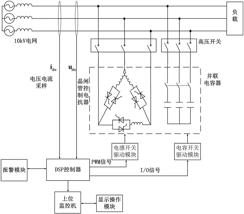
[0042] like figure 1 Shown is the circuit module schematic diagram of the voltage and reactive power control system based on static reactive voltage compensation of the present invention: the voltage and reactive power control system based on static reactive voltage compensation provided by the present invention includes several shunt capacitors and control each Capacitor connected to the grid switch tube, thyristor control reactor, grid voltage sampling module, grid current sampling module, signal conditioning module, control module, inductance switch drive module, capacitive switch drive module, alarm module, monitor and display operation module The thyristor-controlled reactor adopts a delta connection, and each branch is connected in series with a group of reactors, and the anti-parallel thyristor is used as the switching switch of the reactor; the thyristor-controlled reactor is connected in parallel with several parallel capacitors Power grid; the grid voltage sampling m...


PUM


Abstract

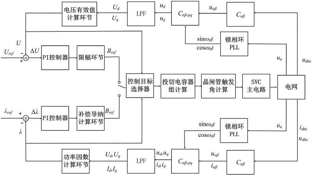
The invention discloses a voltage reactive control system based on static reactive voltage compensation. The system comprises parallel capacitors, a switch tube, a thyristor controlled reactor, a power grid voltage and current sampling module, a signal conditioning module, a control module and a driving module. The power grid voltage and current sampling module is used for sampling data and inputting the data into the control module through the signal conditioning module; and the control module drives the switch tube or a thyristor to work through the driving module. The invention also discloses a control method of the control system. The method comprises the following steps: carrying out power grid sampling; calculating three-phase voltage and current working parameters of a power grid; selecting a control objective; calculating a compensation susceptance value; and calculating switch tube control signals and thyristor conduction angle. The method can carry out reactive power regulation in real time according to system operation information and automatically obtains an optimum operation scheme, thereby ensuring system voltage and power factor stability, reducing distributing line loss, and improving distribution network operation economy and electric energy quality level.

Description

technical field [0001] The invention belongs to the field of power electronics, and in particular relates to a voltage and reactive power control system and a control method based on static reactive voltage compensation. Background technique [0002] With the rapid development of the national economy and the promotion of new rural construction, the living standards of rural residents have been rapidly improved. Especially in recent years, encouraged by the "household appliances to the countryside" policy, all kinds of local electrical appliances have quickly entered the family, and the nature of rural electricity load has changed from the resistive load in the past to the inductive load now, which is reliable for the power supply of the rural distribution network. Higher requirements are put forward for performance, power quality level and reactive power configuration capability. [0003] However, the rural distribution network has the characteristics of large power supply ...

Claims


Application Information

Patent Timeline
IPC IPC(8): H02J3/16H02J3/18
CPCH02J3/16H02J3/1864Y02E40/30
Inventor 刘博何红斌周洁何禹清徐超江卓翰刘菁菁
Owner STATE GRID CORP OF CHINA
Learn More