
Low-power low-cost and high-linearity voltage mode passive mixer

A passive mixer, voltage mode technology, applied in electrical components, modulation and transformation balancing devices, modulation transfer and other directions, can solve the problems of high linearity, high power consumption, poor linearity, etc. Low power consumption, low cost effect

Active Publication Date: 2017-04-26
HANGZHOU CANAANTEK COMM TECH +1
View PDF11 Cites 4 Cited by
  • Summary
  • Abstract
  • Description
  • Claims
  • Application Information

AI Technical Summary

Problems solved by technology

The advantages of primary frequency conversion are simple implementation, low power consumption, and high integration, but the main disadvantage is that the high-frequency local oscillator leaks seriously, which can easily cause signal channel blockage and seriously affect the dynamic range.
Secondary frequency conversion requires two sets of local oscillators, two mixers plus some auxiliary circuits, thereby increasing the design area, power consumption and circuit complexity, but it has high isolation, good linearity and very wide dynamic range
The advantage of the voltage-type active mixer is that the noise figure (NF) is good, and the biggest disadvantage is poor linearity and high power consumption. It is not suitable for systems with a wide dynamic range.
The general load of the current source passive mixer is connected to the transconductance amplifier to convert the current into a voltage, which is convenient for subsequent signal processing. In broadband communication systems, the reason is that the transconductance amplifier needs to consume a lot of current to achieve a large bandwidth

Method used


Image

  • Low-power low-cost and high-linearity voltage mode passive mixer
  • Low-power low-cost and high-linearity voltage mode passive mixer
  • Low-power low-cost and high-linearity voltage mode passive mixer

Examples


Embodiment Construction

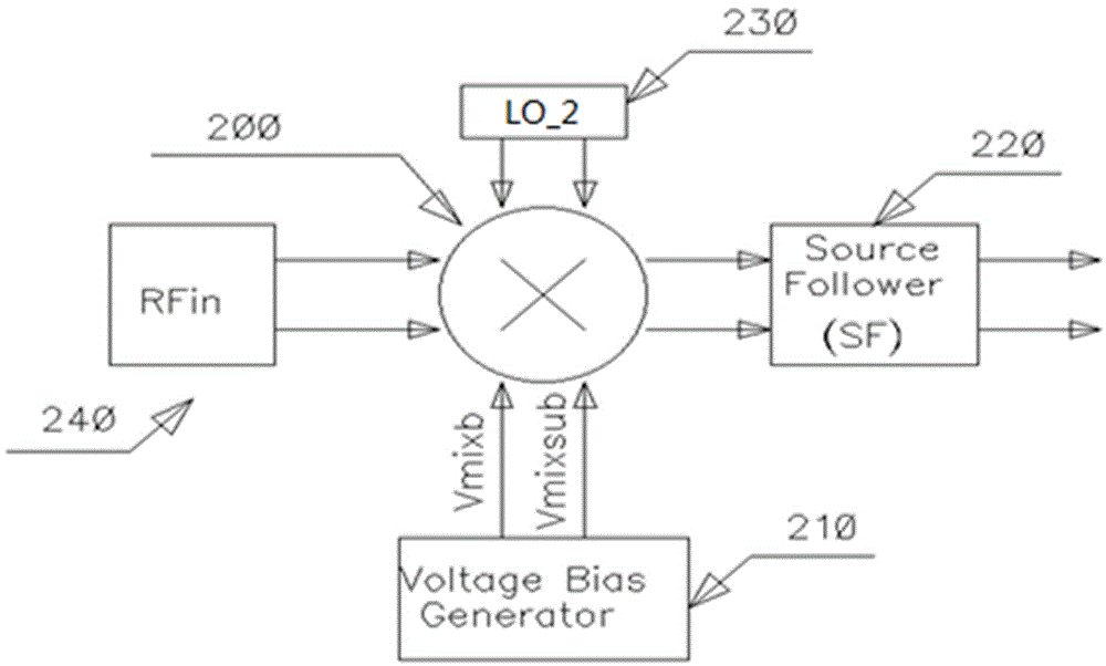
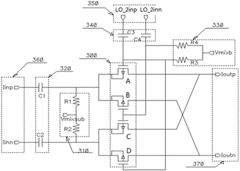
[0022] The following combination Figure 1 to Figure 8 , the present invention will be further elaborated by specifying a preferred specific embodiment.

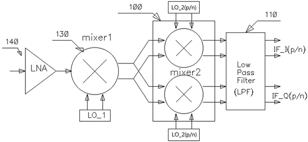
[0023] Such as figure 1 As shown, it is a schematic diagram of the position of the low-power, low-cost and high-linearity voltage-mode passive mixer provided by the present invention on the signal path of the radio frequency receiver, and the voltage-mode passive mixer 100 is used as a The second mixer is arranged between the first mixer (mixer) 130 and the low pass filter (Low Pass Filter, LPF) 110 through circuit connection, and includes two mixing circuits with the same structure. The radio frequency signal amplified by the low noise amplifier (LNA) 140 is mixed with the first local oscillator signal (LO_1) in the first mixer 130, and the output radio frequency signal is mixed with the second local oscillator signal (LO_2) respectively. Frequency mixing in the frequency circuit to output an intermediate frequency signal...


PUM


Abstract

The invention relates to a low-power low-cost and high-linearity voltage mode passive mixer which is arranged on the signal communication channel of a radio frequency receiver to serve as a second mixer of the radio frequency receiver. Through circuits, the mixer is arranged between a first mixer and a low-pass filter. The mixer of the invention consists of two structure-identical frequency mixing circuits. The radio frequency signal outputted from the first mixer is pre-mixed with the local oscillator signals in the frequency mixing circuits respectively to output an intermediate frequency signal which is subjected to filtering of the low-pass filter. The local oscillator signal in each frequency mixing circuit adopts an I / Q (in-phase / quadrature) square wave signal whose duty ratio stands at 25%. With the two frequency mixing circuits, I / Q frequency conversion can be realized. The mixer of the invention can solve the shortcomings represented by the second mixer in the form of a voltage type active mixer and a current type passive mixer in a second frequency conversion structured receiver in the prior art. At the same time, the mixer of the invention also features as a low-power, low-cost, high linearity, and wideband radio frequency receiver.

Description

technical field [0001] The invention relates to a voltage mode passive mixer, in particular to a voltage mode passive mixer with low power consumption, low cost and high linearity, and belongs to the technical field of radio frequency receivers. Background technique [0002] With the continuous expansion of the application field of wireless communication technology, people's demand for equipment such as portable wearables, smart homes, smart medical care and high-definition positioning systems is rapidly increasing. For these devices, the requirements for design indicators such as higher sensitivity, smaller size, lower energy consumption, and wider dynamic range are becoming more and more stringent. The mixer is a very important module in the RF receiving system of these devices. Its function is to extract the intermediate frequency signal after mixing the RF signal and the local oscillator signal. As far as the current technical level and widely used system architecture a...

Claims


Application Information

Patent Timeline
IPC IPC(8): H03D7/14
CPCH03D7/1441Y02D30/70
Inventor 鲍荣涛谢婷婷倪文海徐文华
Owner HANGZHOU CANAANTEK COMM TECH
Learn More