Lower plate sealing structure of gas-gas heat exchanger

A gas-type heat exchanger and sealing structure technology, applied in the direction of heat exchanger sealing device, heat exchanger shell, heat exchange equipment, etc., can solve the problems of plate corrosion, mixing of cold and hot fluids, easy failure, etc., and achieve production costs. Low, simple sealing structure, simple structure effect

Inactive Publication Date: 2017-05-03
浙江鼎诚环保科技有限公司
View PDF9 Cites 2 Cited by
  • Summary
  • Abstract
  • Description
  • Claims
  • Application Information

AI Technical Summary

Problems solved by technology

[0004] In the prior art, only metal plates are often used to separate the flue gas, which will easily cause corrosion of the plates after a long time, and the seals are also prone to failure when they are exposed to the flue gas environment for a long time
[0005] People use heat exchange tubes made of PTFE to overcome the problem of flue gas corrosion. In large-flux heat exchangers, heat exchange tubes with large sizes and long lengths are often used. The thermal expansion and contraction of the heat exchange tubes, that is, the expansion and contraction of the heat exchange tubes on the bottom plate, is more serious. Once they shrink into the shell side of the heat exchanger, it will cause the mixing of hot and cold fluids and destroy the operation of the entire production line.
[0006] The Chinese utility model patent with the authorized announcement number CN 202814194 U discloses a bottom plate of a tubular air-gas heat exchanger, which includes a bottom orifice plate, and heat exchange tubes are welded on the bottom orifice plate to fix the heat exchange tubes. Prevent it from shrinking back into the shell side of the heat exchanger. This method uses a welding process, which is troublesome, and the heat exchange tube has no room to move. After long-term use, the material at the weld is prone to fatigue and breakage, which affects heat transfer. service life of the device

Method used


Image

  • Lower plate sealing structure of gas-gas heat exchanger
  • Lower plate sealing structure of gas-gas heat exchanger

Examples


Embodiment 1

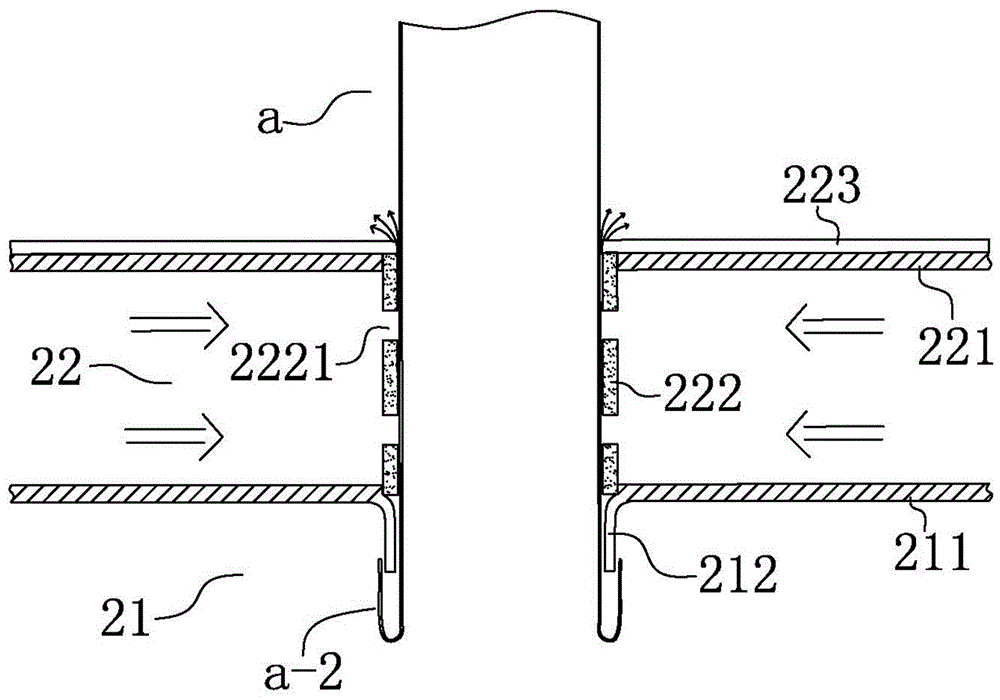
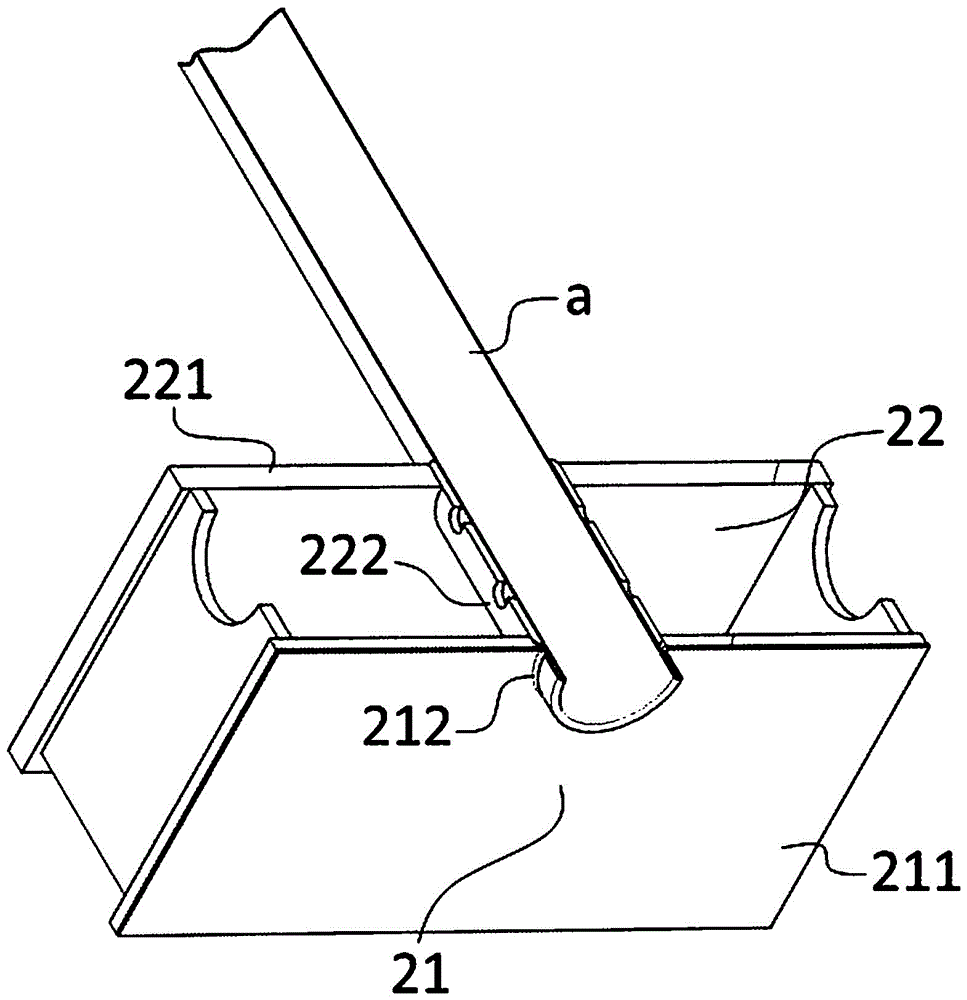
[0028] Example 1: Reference figure 1 and figure 2 , a lower plate sealing structure of a gas-gas heat exchanger, comprising a heat exchange tube limiting portion 21 and a lower plate high pressure air sealing portion 22 located above the heat exchange tube limiting portion 21;

[0029] The heat exchange tube limiting part 21 includes a first lower orifice plate 211, and the first lower orifice plate 211 is provided with a first lower hole for the heat exchange tube a to pass through. The lower surface of the first lower orifice plate 211 , The edge of the first lower hole is also provided with a limit protrusion 212, the outer surface of the limit protrusion 212 is a curved arc surface, and it is gathered inward from top to bottom, and the lower end of the heat exchange tube a is set Limiting part a-2, the limiting part a-2 is a lower edge formed by turning the lower edge of the heat exchange tube a outward, and the lower edge is formed with the outer wall of the heat exchan...


PUM


Abstract

The invention discloses a lower plate sealing structure of a gas-gas heat exchanger, and relates to the technical field of end plates of heat-exchange equipment. The lower plate sealing structure comprises a heat exchange pipe limiting part and a lower plate high-pressure gas sealing part located above the heat exchange pipe limiting part; the heat exchange pipe limiting part comprises a first lower hole plate and a limiting protrusion, and the lower end of a heat exchange pipe is provided with a limiting part matched with the limiting protrusion; and the lower plate high-pressure gas sealing part is located in interlayer space between a first lower hole plate and a second lower hole plate, and comprises a part of heat exchange pipe and a lower plate sealing sleeve connected to the heat exchange pipe in a sleeving manner. By means of the sealing structure, the heat exchange pipe and the lower hole plates form a clamped structure, the heat exchange pipe is limited only during shrinkage, the problem of material fatigues at the welding position can be avoided while shrinkage of the heat exchange pipe is avoided, and the lower plate sealing structure is simple in structure and durable.

Description

technical field [0001] The invention relates to the technical field of end plates of heat exchange equipment, in particular to a lower plate sealing structure of a gas-gas heat exchanger. Background technique [0002] With the depletion of oil and coal, energy issues are becoming more and more prominent in front of people. In addition to the development of new energy sources, the conservation and reuse of existing energy sources have also become the focus of people's research. [0003] In energy utilization technology, a heat exchanger is a device for exchanging heat between hot and cold fluids without direct contact. The tube-type gas-gas heat exchanger has a wide range of applications in the fields of coal-fired boilers, waste incineration power generation, etc. Applications. [0004] In the prior art, only metal plates are often used to separate the flue gas, which will easily cause corrosion of the plates after a long time, and the seals are also prone to failure when e...

Claims


Application Information

Patent Timeline
Patent Type & Authority Applications(China)
IPC IPC(8): F28F9/06F28F11/00F28F19/00
CPCF28F9/06F28F11/00F28F19/00
Inventor 沈煜晖吴涛刘桂梅曲啸辉
Owner 浙江鼎诚环保科技有限公司
Why Eureka
Try Eureka