
Micro-fluidic chip and preparation method and application thereof

A technology of microfluidic chips and microfluidic channels, applied in chemical instruments and methods, laboratory containers, laboratory utensils, etc., can solve the problems of cumbersome steps, low separation efficiency, dead cells, etc., and achieve comprehensive Low cost, good application prospect, simple operation effect

Active Publication Date: 2017-05-10
SHANGHAI JIAO TONG UNIV
View PDF3 Cites 7 Cited by
  • Summary
  • Abstract
  • Description
  • Claims
  • Application Information

AI Technical Summary

Problems solved by technology

The disadvantages are: the separation efficiency is not high, dead cells are obtained, and molecular biological analysis of CTCs cannot be performed.
Circulating tumor DNA (ctDNA) and tumor-associated protein markers currently mainly rely on chemical reagent separation methods, facing the problem of low purity and low concentration of separation
The separation methods of exosomes are mostly centrifugation, chemical reagent sedimentation and immunomagnetic bead methods, which also have many problems, such as cumbersome steps, time-consuming and labor-consuming, damage to exosomes, separation efficiency, etc.

Method used


Image

  • Micro-fluidic chip and preparation method and application thereof
  • Micro-fluidic chip and preparation method and application thereof
  • Micro-fluidic chip and preparation method and application thereof

Examples


Embodiment Construction

[0029] The present invention will be further described below in conjunction with the accompanying drawings.

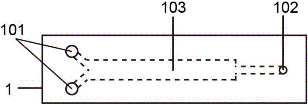
[0030] Such as figure 1 with 2 As shown, the structure of the encapsulation layer 1 includes an encapsulation layer inlet 101, an encapsulation layer outlet 102 and an encapsulation layer microfluidic channel 103, and the three are connected to each other, and liquid can enter from the encapsulation layer inlet 101 and flow through the encapsulation layer microfluidic channel 103. The channel 103 exits from the outlet 102 of the encapsulation layer.

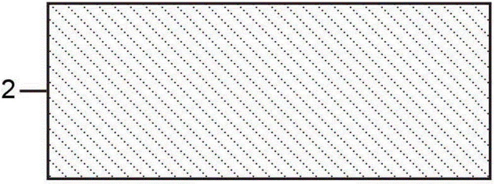
[0031] Such as image 3 with 4 As shown, the base layer 2 is a plate-like structure without holes.

[0032] Such as Figure 5 with 6 As shown, the microfluidic chip contains three porous membrane layers and three support layers. For ease of distinction, the three-layer porous membrane layers are named respectively as the first porous membrane layer 3, the second porous membrane layer 5 and the third porous membrane...


PUM

PropertyMeasurementUnit
Aperture sizeaaaaaaaaaa

Abstract

The invention provides a micro-fluidic chip, which comprises an encapsulation layer, a substrate layer, a porous film layer and a support layer, wherein the porous film layer and the support layer are arranged between the encapsulation layer and the substrate layer; the encapsulation layer is connected to the porous film layer; the substrate layer is connected with the support layer; the encapsulation layer is provided with an encapsulation layer inlet, an encapsulation layer micro-fluidic channel and an encapsulation layer outlet; the porous film layer is provided with a through hole, so that the liquid can flow into the through hole from the encapsulation layer micro-fluidic channel; and the support layer is provided with a support layer inlet, a support layer micro-fluidic channel and a support layer outlet. The invention further relates to a preparation method and application of the micro-fluidic chip. Compared with the prior art, the micro-fluidic chip has the advantages of being simple in operation, time-saving, labor-saving and relatively low in comprehensive cost, especially has the characteristic of synchronously separating different sizes of substances through one operation, and the subsequent analysis efficiency can be greatly improved, therefore, the micro-fluidic chip has a good application prospect in the field of clinical diagnosis, food sanitation, environment monitoring, drug development, biochemistry, micro-chemical engineering, battlefield bio-detection and the like.

Description

technical field [0001] The invention relates to a chip and its preparation method and application, in particular to a microfluidic chip and its preparation method and application. Background technique [0002] Microfluidics is a technology that precisely controls and manipulates microscale fluids, especially submicron structures. Through the control of fluid at the microscale, microfluidic technology began to rise in the 1980s, and has been developed in the directions of DNA chip, lab-on-a-chip, micro-sampling technology, and micro-thermodynamic technology. Microfluidic analysis chip was originally called "lab-on-a-chip" in the United States, and "micrototal analytical systems" in Europe. ) to realize the main platform, which can integrate the basic operation units such as sample preparation, reaction, separation, and detection in the biological, chemical, and medical analysis processes into a micron-scale chip, and automatically complete the entire analysis process. Micro...

Claims


Application Information

Patent Timeline
IPC IPC(8): B01L3/00
CPCB01L3/502715B01L3/502753B01L3/502769B01L2300/0864B01L2300/087B01L2300/0877B01L2300/0887
Inventor 崔大祥郅晓邓敏
Owner SHANGHAI JIAO TONG UNIV
Learn More