Method for electron beam welding of hollow flat tube type parts

A technology of electron beam welding and electron beam, which is applied in the field of electron beam welding of hollow flat tube parts, can solve the problems that hollow flat tubes cannot be welded at the same time, welding efficiency needs to be improved, and welding methods are lacking, so as to avoid welding defects and solve Difficult to weld and improved welding efficiency

Active Publication Date: 2017-05-10
AECC AERO SCI & TECH CO LTD
View PDF5 Cites 10 Cited by
  • Summary
  • Abstract
  • Description
  • Claims
  • Application Information

AI Technical Summary

Problems solved by technology

However, the above two welding methods cannot realize the simultaneous welding of the upper and lower sides of the hollow flat tube, so the welding efficiency needs to be improved
[0003] Furthermore, for two hollow flat tube parts that need to be fixed by welding, if at least one side of the welded part is shielded, there is currently no effective welding method.

Method used


Image

  • Method for electron beam welding of hollow flat tube type parts
  • Method for electron beam welding of hollow flat tube type parts
  • Method for electron beam welding of hollow flat tube type parts

Examples


Embodiment 1

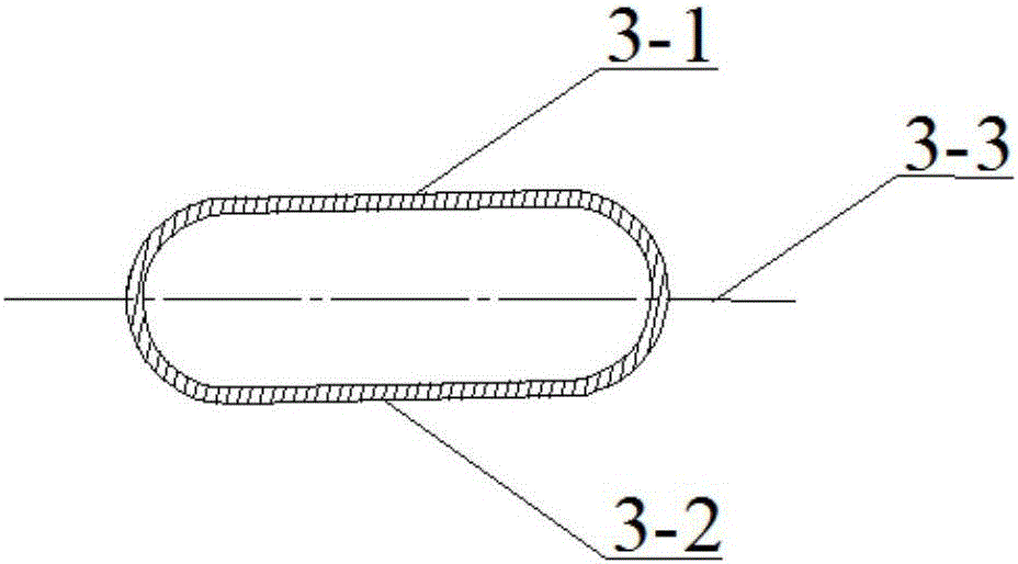
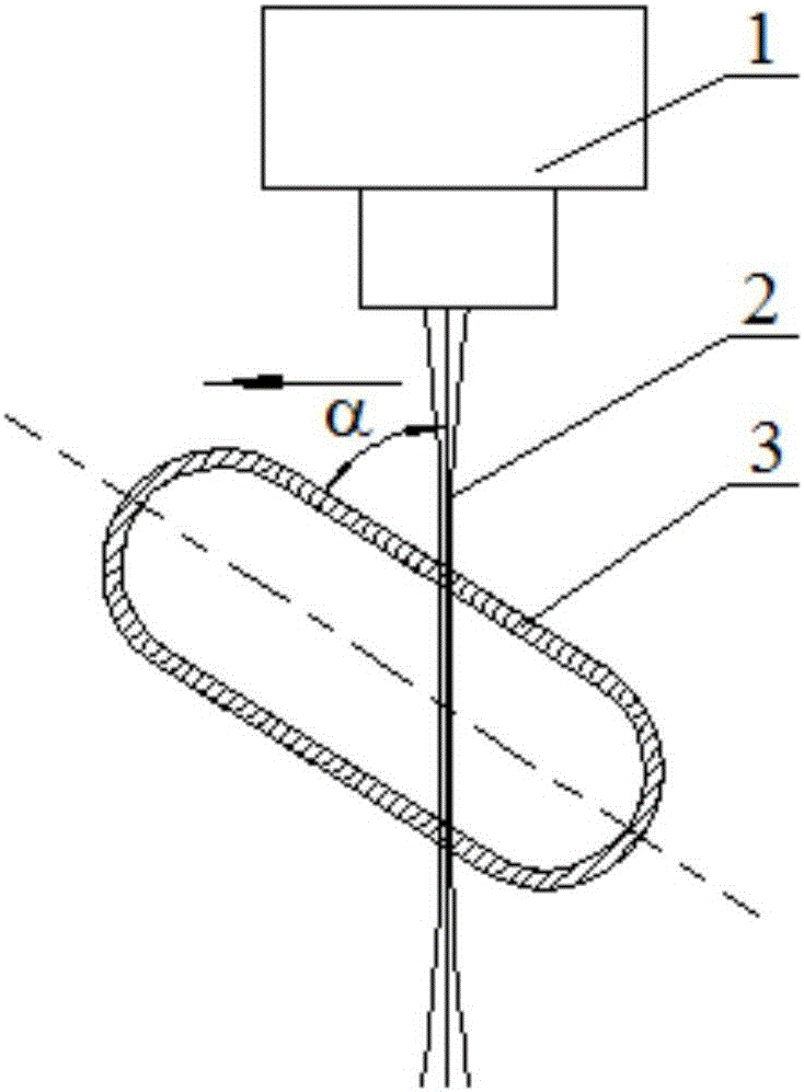
[0028] Hollow flat tube parts in the present embodiment, material is TC4 titanium alloy, and its hollow flat tube 3 is as figure 1 As shown, including the upper side 3-1 and the lower side 3-2, the position where the upper side and the lower side meet is an arc surface, and the axis of symmetry of the upper side and the lower side is the long axis 3-3 of the hollow flat tube. The wall thickness of the flat tube is 1.8 mm to 2.2 mm, and there is no shielding part on both sides of the welding part.

[0029] In this embodiment, the electron beam acceleration voltage of the electron beam generator 1 is 60KV-150KV, the welding speed (moving speed of the electron beam generator) is 10mm / sec-20mm / sec, and the electron beam current varies with the welding thickness according to the following formula :

[0030] E=(U·I) / (V·T)

[0031] Where E is the input energy per unit time and unit thickness of the welding part, U is the electron beam acceleration voltage, I is the electron beam cu...

Embodiment 2

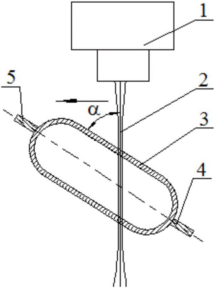
[0040] In this embodiment, for Figure 5 The shown casing main body 7 and the pipe joint 9 are welded, and the welded parts of the pipe joint 9 and the casing main body 7 are hollow flat tubes (see Figure 4 ), the length L=60.5mm of the cross-section of the hollow flat tube 3, the width B=30mm, the wall thickness is 2.0mm, and the lower side of the welding part 8 is shielded by the structure on the casing main body 7 (see Figure 5 ); The materials of casing main body 7 and pipe joint 9 are GH4169 superalloy.

[0041] In this embodiment, the electron beam accelerating voltage of the electron beam generator 1 is 150KV, the electron beam current varies with the welding depth (see step 3 below), and the welding speed (moving speed of the electron beam generator) is 20mm / s.

[0042] In this embodiment, the electron beam energy absorbing plate 6 is equipped, and the arc starting plate 4 and the arc receiving plate 5 are fixedly connected by tack welding on both sides of the weldi...


PUM


Abstract

The invention discloses a method for electron beam welding of hollow flat tube type parts. Firstly, two hollow flat tube type parts are installed on a welding worktable in an electron beam welding machine vacuum chamber, the installing positions of the two hollow flat tube type parts are adjusted to make included angles formed by the upper side faces of their hollow flat tubes and an electron beam emitted by an electron beam generator range from 45 degrees to 90 degrees; vacuumizing is performed to make the pressure intensity in the electron beam welding machine vacuum chamber smaller than or equal to 1.0*3 mbar; finally, the welding worktable or the electron beam generator is moved at a constant speed to introduce the electron beam from a welding part on one side of the long axes of the hollow flat tubes and is moved to the tail end of the welding part on the other side of the long axes of the hollow flat tubes in the long-axis direction, namely welding of the two hollow flat tube type parts is completed. The welding of two faces of the hollow flat tubes is achieved and the welding efficiency is improved by at least one time by adopting the method, the problem that shielded portion parts are difficult to weld is solved, and the method has wide application prospect in the field.

Description

technical field [0001] The invention belongs to the field of welding technology, and relates to the welding of flat tube parts, in particular to a method for electron beam welding of hollow flat tube parts. Background technique [0002] When the hollow flat tube parts are welded by electron beam, the existing welding methods mainly include two kinds: (1) if the hollow flat tube shape of the hollow flat tube parts is standardized, the hollow flat tube parts and the electron beam generator Carry out relative rotation, and continuously weld the welding part of the hollow flat tube; (2) If the shape of the hollow flat tube of the hollow flat tube part is not standardized, fix the electron beam generator, and turn the hollow flat tube once or several times Parts, complete the welding of all welding parts of hollow flat tube parts in sections. However, both of the above two welding methods cannot realize the simultaneous welding of the upper and lower sides of the hollow flat tub...

Claims


Application Information

Patent Timeline
Patent Type & Authority Applications(China)
IPC IPC(8): B23K15/00B23K101/06
CPCB23K15/00B23K15/0053B23K2101/06
Inventor 乔雷张校宇赵小勇李芳张强金涛程立卿颖刘威李林陈鹏飞
Owner AECC AERO SCI & TECH CO LTD
Why Eureka
Try Eureka