Station crossing device and method for shield tunneling machine

A shield machine and station-passing technology, which is applied in the fields of earth drilling, transportation and packaging, mining equipment, etc., can solve the problems of slow moving speed, slow construction period, and difficult work, and achieve consistency, easy operation, and work Effect of Difficulty Reduction

Inactive Publication Date: 2017-05-10
CHINA RAILWAY NO 2 ENG GRP CO LTD
View PDF8 Cites 12 Cited by
  • Summary
  • Abstract
  • Description
  • Claims
  • Application Information

AI Technical Summary

Problems solved by technology

[0003] Currently, there are two commonly used methods for the passing of the existing shield machine: a. During the passing of the shield machine, a trailer is used to carry the shield machine, a roller is placed on the bottom of the trailer, and a steel plate is laid under the roller. Rolling on the steel plate makes the trailer move forward. The disadvantage is that the moving speed is relatively slow. After the shield machine passes through the station, it must be moved to the counter force starting frame to

Method used


Image

  • Station crossing device and method for shield tunneling machine
  • Station crossing device and method for shield tunneling machine
  • Station crossing device and method for shield tunneling machine

Examples


Embodiment 1

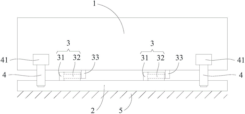
[0047] Such as Figure 1-5 As shown, a shield machine passing device according to the present invention includes:

[0048] The bracket 2 is used to receive the shield machine 1 at the exit of the tunnel at one end of the site, carry the shield machine 1 during the process of transferring the shield machine 1, and use the excavation point of the shield machine 1 at the other end of the site as the shield The counter force frame for the excavation of mechanism 1;

[0049] The piston mechanism includes two piston assemblies 3, each of which is connected to the shield machine 1 and the bracket 2 for horizontal movement between the shield machine 1 and the bracket 2;

[0050] The jacking mechanism includes four jacking assemblies 4, and each jacking assembly 4 is connected to the shield machine 1 for jacking the shield machine 1 and the bracket 2 higher than the foundation 5 by about 200mm.

[0051] As a preferred solution of this embodiment, the shield machine 1 is provided wit...

Embodiment 2

[0057] Such as Figure 1-6 As shown, a shield machine passing method according to the present invention, using the shield machine passing device as described in Embodiment 1, is characterized in that it includes the following steps:

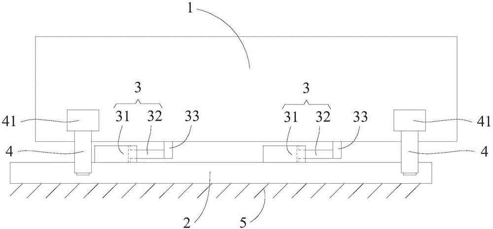
[0058] A. If figure 2 As shown, the shield machine 1 moves: the piston mechanism moves to drive the shield machine 1 to move relative to the bracket 2;

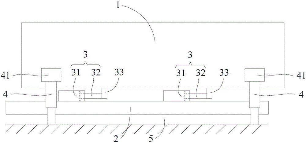
[0059] B. If image 3 As shown, the shield machine 1 is jacked up: the jacking mechanism jacks up the shield machine 1, and drives the bracket 2 away from the foundation 5;

[0060] C. If Figure 4 As shown, the bracket 2 moves: the piston mechanism resets, driving the bracket 2 to move relative to the shield machine 1;

[0061] D. If Figure 5 As shown, the shield machine 1 lands: the jacking mechanism resets;

[0062] E. Cycle operation: repeat the steps A-D until the shield machine 1 passes through the station.

[0063] Using a shield machine passing method described in the present in...


PUM


Abstract

The invention discloses a station crossing device for a shield tunneling machine. The station crossing device comprises a bracket, a piston mechanism and a jacking mechanism; the bracket is used for receiving and bearing the shield tunneling machine and serves as a reaction frame used when the shield tunneling machine starts tunneling, the piston mechanism comprise a piston component connected with the shield tunneling machine and the bracket and is used for horizontal moving between shield tunneling machine and the bracket, and the jacking mechanism comprises a jacking component connected to the shield tunneling machine and is used for jacking the shield tunneling machine and the bracket to be separated from a foundation. By applying the device, self-waling movement of the shield tunneling machine and the bracket is achieved by means of cooperation movement of the piston mechanism and the jacking mechanism, and a roller steel plate structure or a rail transportation structure which can enable the bracket to move does not need to be arranged for the bracket separately; meanwhile, after the shield tunneling machine crosses a station, the bracket directly serves as the reaction starting frame of the shield tunneling machine, the piston mechanism supports the shield tunneling to tunnel forwards, and the reaction starting frame does not need to be installed independently. The device is simple in structure and easy and convenient to operate, the station crossing working difficulty of the shield tunneling station is greatly reduced, the working time is shortened, the construction efficiency is improved, and the cost is reduced.

Description

technical field [0001] The invention relates to the technical field of tunnel engineering, in particular to a station passing device and method for a shield machine. Background technique [0002] In the construction of urban subway tunnels, shield machines play an increasingly important role. After the shield machine completes the construction of a section, it needs to move through the subway station—referred to as the shield passing through the station to construct the next section tunnel. [0003] Currently, there are two commonly used methods for the passing of the existing shield machine: a. During the passing of the shield machine, a trailer is used to carry the shield machine, a roller is placed on the bottom of the trailer, and a steel plate is laid under the roller. Rolling on the steel plate makes the trailer move forward. The disadvantage is that the moving speed is relatively slow. After the shield machine passes through the station, it must be moved to the count...

Claims


Application Information

Patent Timeline
IPC IPC(8): E21F13/00E21D9/06
CPCE21F13/006E21D9/06
Inventor 陈勇光陈强陈卓
Owner CHINA RAILWAY NO 2 ENG GRP CO LTD
Why Eureka
Try Eureka