Vibration feeding burner and its control method

A vibrating feeder and burner technology, which is applied in the direction of combustion method, solid fuel combustion, and controlled combustion, can solve the problems of low temperature control accuracy and frequent coal addition, so as to improve accuracy, save man-hours, and save energy Effect

Active Publication Date: 2019-01-15
湖南驱动源电气技术有限公司
View PDF8 Cites 0 Cited by
  • Summary
  • Abstract
  • Description
  • Claims
  • Application Information

AI Technical Summary

Problems solved by technology

[0006] The main purpose of the present invention is to provide a vibrating feeding burner, which aims to solve the problems of low temperature control accuracy and frequent coal addition in existing burners

Method used


Image

  • Vibration feeding burner and its control method
  • Vibration feeding burner and its control method
  • Vibration feeding burner and its control method

Examples


Embodiment Construction

[0059] The specific embodiments of the present invention will be further described below in conjunction with the accompanying drawings. It should be noted here that the descriptions of these embodiments are used to help understand the present invention, but are not intended to limit the present invention. In addition, the technical features involved in the various embodiments of the present invention described below may be combined with each other as long as they do not constitute a conflict with each other.

[0060] The invention proposes a vibrating feeding material burner.

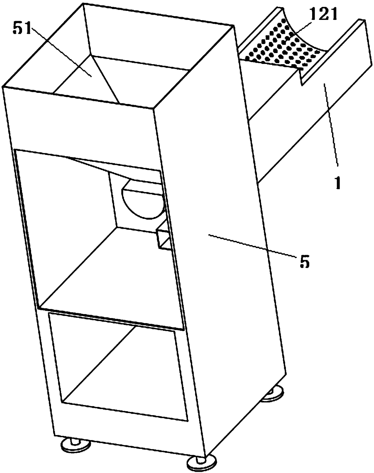
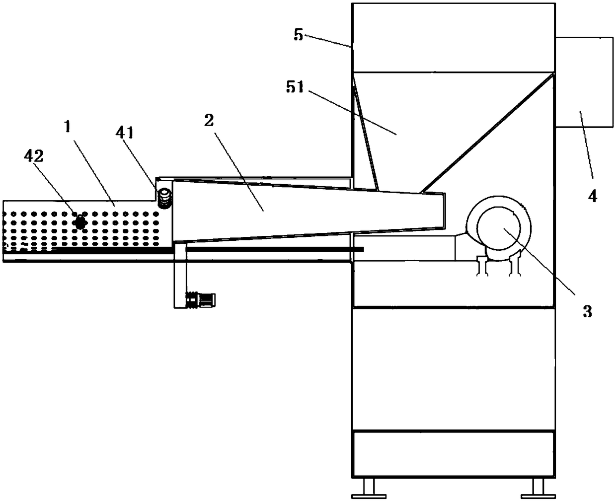
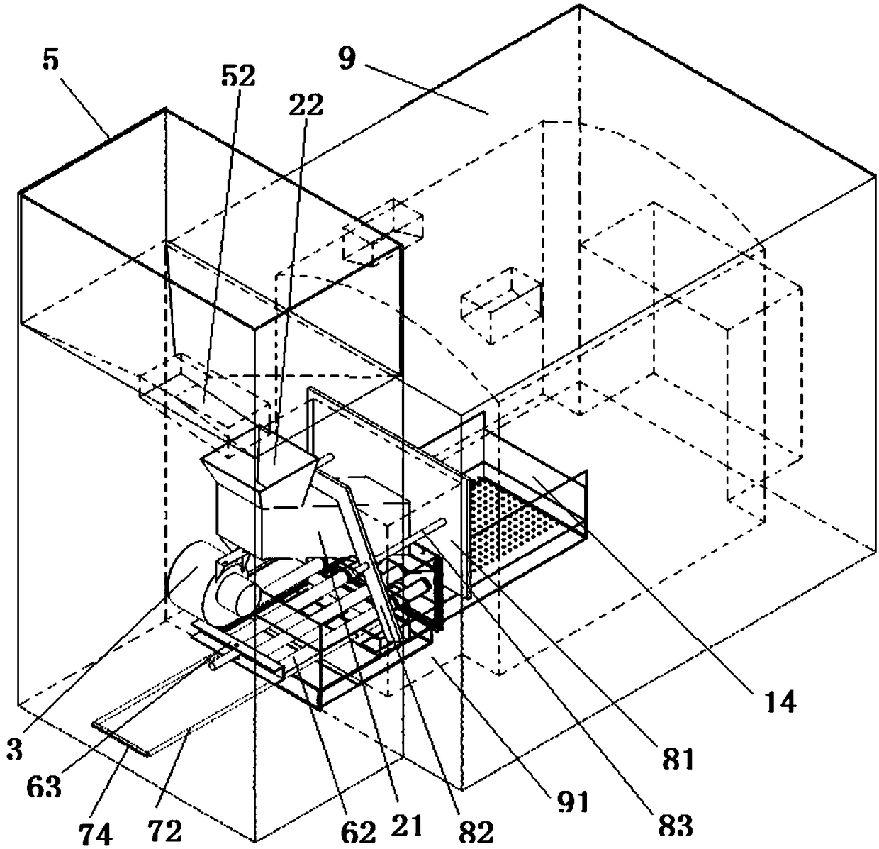
[0061] figure 1 It is a perspective view of a vibrating feed material burner proposed by an embodiment of the present invention. figure 2 for figure 1 sectional view. image 3 for figure 1 Schematic diagram of the structure of the medium-vibration feeding burner installed in the stove chamber. Figure 4 for figure 1 Schematic diagram of the structure of the medium-vibration feeding burner instal...


PUM


Abstract

The invention discloses a vibrating feed combustor, comprising a combustion grate, a feeder, a blower and a controller, wherein the combustion grate comprises a grate enclosure, a first division plate and a second division plate arranged horizontally are arranged in the grate enclosure to divide the space encircled by the grate enclosure into a combustion trough, a combustion trough air flue and a slag receiving chamber, the first division plate is provided with vents, the combustion trough air flue is provided with an air inlet in one side in the horizontal direction, and the blower is communicated with the combustion trough air flue via the air inlet; the feeder is an electric vibrating feeder and comprises a feed pipe, the lower port of the feed pipe is arranged above the combustion trough, a first temperature sensor is arranged in the combustion grate, a second temperature sensor is arranged in a baking room, and the controller is connected with the blower, the electric vibrating feeder, the first temperature sensor and the second temperature sensor and used for controlling the frequency or magnitude of the electric vibrating feeder and the air quantity of the blower according to the temperature in the combustion trough and the difference between the current temperature in the baking room and a preset temperature.

Description

technical field [0001] The invention belongs to the technical field of combustion equipment, and in particular relates to a vibrating feeding material combustion machine and a control method thereof. Background technique [0002] A hot blast stove is a device that uses hot air for drying or heating in order to meet the requirements of higher temperature baking operations. Its working principle is to use a burner to burn fuel, and the high-temperature combustion gas obtained after the combustion reaction is purified to form hot air. , sent to the baking room to heat the material. [0003] Fuel in the furnace of existing hot blast stoves usually needs to be added manually. If the number of coal additions is reduced, more fuel needs to be added at one time, resulting in an increase in the combustion surface, and the heat generated by combustion exceeds the demand, making it difficult to control the temperature and the heating temperature is unstable. and, in the existing hot b...

Claims


Application Information

Patent Timeline
Patent Type & Authority Patents(China)
IPC IPC(8): F23K3/16F23B90/04F23N1/02
CPCF23B90/04F23K3/16F23N1/025
Inventor 陈宇轩陈娟陈俊
Owner 湖南驱动源电气技术有限公司
Why Eureka
Try Eureka