
Wearable equipment and method and device for detecting wearing state of same

A technology for wearable devices and detection units, applied in measuring pulse rate/heart rate, instruments, electrical digital data processing, etc., can solve the problems of increasing the difficulty of bracelet technology, increasing equipment power consumption, increasing power consumption, etc., to increase the difficulty of design , reduce adverse effects, and reduce power consumption

Active Publication Date: 2017-05-10
GUANGDONG TRANSTEK MEDICAL ELECTRONICS CO LTD
View PDF4 Cites 17 Cited by
  • Summary
  • Abstract
  • Description
  • Claims
  • Application Information

AI Technical Summary

Problems solved by technology

[0004] However, the method of judging whether the wristband is worn by adding circuits and contact points on the wristband, first of all, needs to increase the electronic components to realize it, which will increase the cost of the product; secondly, adding circuits to the wristband will inevitably increase the function. consumption, weakening the battery life of the bracelet; again, it will also bring difficulty in structural design, as well as the electrical connectivity between the main body of the bracelet and the wristband, which will increase the difficulty of the craftsmanship of the bracelet and make it difficult to realize
In addition, by comparing the three-axis acceleration characteristic range with the preset range, the heart rate value is used to determine whether the bracelet is worn. Although no additional cost or structure is required, the heart rate measurement will be affected by factors such as ambient light, wearing method, wearing The location and other factors affect the signal quality, and it takes too much time to collect signal data, occupying CPU resources to calculate the heart rate value, resulting in longer judgment time and increased power consumption of the device

Method used

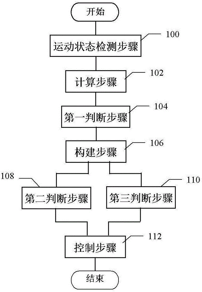
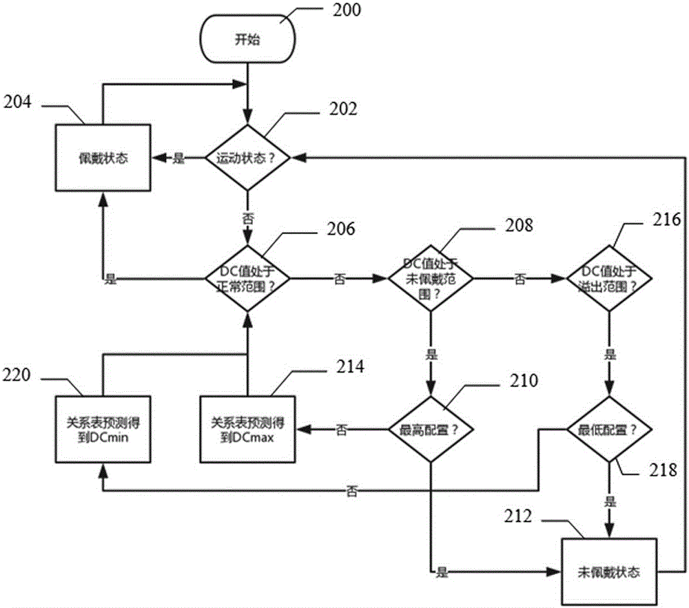
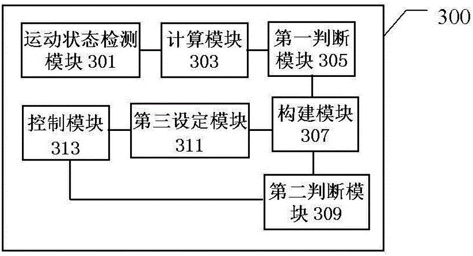

Image

  • Wearable equipment and method and device for detecting wearing state of same
  • Wearable equipment and method and device for detecting wearing state of same
  • Wearable equipment and method and device for detecting wearing state of same

Examples


Embodiment Construction

[0029]When the light passes through the skin tissue and then reflects to the photosensitive sensor, the light is attenuated to a certain extent. In the case of no large-scale movement of the detection part, such as muscles, bones, veins and other connected tissues, the absorption of light is basically unchanged. However, blood is different. Due to the flow of blood in the blood vessel, the volume of the blood vessel at a certain position will change, and the absorption of light will also change accordingly. When converting light into electrical signals, it is precisely because the absorption of light by blood vessels changes and the absorption of light by other tissues is basically unchanged, the obtained signal can be divided into direct current DC signal (intensity of reflected signal) and alternating current AC signal (the amount of change in the reflected signal). By extracting the AC signal, the characteristics of blood flow can be reflected. This technique is called ph...


PUM


Abstract

The invention discloses a method and a device for detecting wearing state of wearable equipment. The method includes: the step of calculating, collecting light signals according to on-off condition of light for detecting heart rate, and calculating a differential signal value DCVAL; the step of first judgment, determining whether the DCVAL is within a non-worn range, a normal range or an excessive range according to a relationship between the DCVAL and preset lower limit value, upper limit value and maximum value, wherein when the DCVAL is within the normal range, the wearable equipment is determined in a worn state. According to the method and the device for detecting the wearing state of the wearable equipment and the wearable equipment comprising the device, whether the wearable equipment is in a worn state or not can be recognized in a manner of simple calculation, short consumed time and less power consumption without adding additional structure and increasing design difficulty; when the circumstance that the wearable equipment is not worn is determined, a heart rate detection unit comprising an LED lamp can be turned off, so that power consumption can be reduced, and adverse influence on life can be reduced.

Description

technical field [0001] The present invention relates to a detection method and device, in particular to a method and device for detecting whether a wearable device is worn and a wearable device including the device. Background technique [0002] Wearable devices such as wristbands are small in size and have limited internal space, so the battery capacity is also small in size and limited in capacity. Therefore, in order to achieve long-term use, the power consumption must be very low. The heart rate detection unit in the wearable device is a very power-consuming module. When it is worn normally, the heart rate function will be turned on to measure the heart rate. However, if the bracelet is removed and left unused, it is necessary to turn off the heart rate measurement in time to reduce unnecessary power consumption. Moreover, the heart rate measurement is always on, and the LED light will always flash, which will also affect the user's daily life. For example, when you a...

Claims


Application Information

Patent Timeline
IPC IPC(8): G06F1/16A61B5/024
Inventor 龙厚成
Owner GUANGDONG TRANSTEK MEDICAL ELECTRONICS CO LTD
Learn More