Hybrid optoelectronic encoder installation error compensation value determination system and method

A photoelectric encoder, installation error technology, applied in the direction of electromechanical devices, electrical components, electric components, etc., can solve the problem of affecting the accuracy of servo motor startup and operation control, the inability of the servo motor to start or reverse, and reducing the efficiency of the control system, etc. , to achieve the effect of easy popularization, simple structure and simplified implementation steps

Inactive Publication Date: 2017-05-10
XIAN UNIV OF SCI & TECH
View PDF7 Cites 0 Cited by
  • Summary
  • Abstract
  • Description
  • Claims
  • Application Information

AI Technical Summary

Problems solved by technology

However, like other types of sensors, the assembly error of the hybrid photoelectric encoder during installation will cause an error between the actual rotor position of the servo motor and the rotor position detected by the hybrid photoelectric encoder. The existence of this detection error It will cause unexpected and uncontrollable direct-axis current, which will affect the accuracy of the start-up and operation control of the servo motor, reduce the efficiency of the control system, and cause the servo motor to fail to start or reverse in severe cases
[0003] At present, the detection of the installation position of the hybrid photoelectric encoder usually adopts the method of manual repeated experiments, and the installation position of the hybrid photoelectric encoder is adjusted until the accuracy requirements are met. The detection cost is high, the efficiency is low, and the manpower and material resources are high.

Method used


Image

  • Hybrid optoelectronic encoder installation error compensation value determination system and method
  • Hybrid optoelectronic encoder installation error compensation value determination system and method

Examples


Embodiment Construction

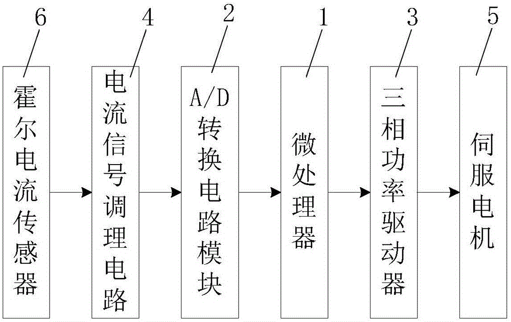
[0036] Such as figure 1 As shown, the hybrid photoelectric encoder installation error compensation value determination system of the present invention includes a microprocessor 1 and a Hall current sensor 6 for real-time detection of the DC bus current that supplies power to the servo motor 5. The microprocessor The input terminal of the device 1 is connected with an A / D conversion circuit module 2, and the input terminal of the A / D conversion circuit module 2 is connected with a current signal conditioning circuit 4 for amplifying and conditioning the signal output by the Hall current sensor 6, so The output terminal of the Hall current sensor 6 is connected with the input terminal of the current signal conditioning circuit 4, and the output terminal of the microprocessor 1 is connected with a three-phase power driver 3 for driving a servo motor 5 equipped with a hybrid photoelectric encoder , the servo motor 5 is connected to the output end of the three-phase power driver 3 ...


PUM


Abstract

The invention relates to a hybrid optoelectronic encoder installation error compensation value determination system and method. The system comprises a microprocessor, a Hall current sensor, an A/D conversion circuit module, a current signal conditioning circuit and a three-phase power driver for driving a servo motor provided with a hybrid optoelectronic encoder. The method includes the following steps that: firstly, direct-current bus-bar current signals are acquired and processed when an installation error compensation value is zero; secondly, direct-current bus-bar current signals are acquired and processed when the installation error compensation value is an installation error compensation minimum angle; thirdly, X and Y are compared with each other according to conditions, and the installation error compensation value of the hybrid optoelectronic encoder is adjusted; and fourthly, the installation error compensation value of the hybrid optoelectronic encoder is determined. The hybrid optoelectronic encoder installation error compensation value determination system and method of the invention have the advantages of reasonable design, convenient implementation, low cost, convenient use and operation, high adaptability, high practicability and excellent use effects, and do not need to consume too many manpower and material resources, and are suitable for being popularized.

Description

technical field [0001] The invention belongs to the technical field of encoder installation position error correction, and in particular relates to a system and method for determining an installation error compensation value of a hybrid photoelectric encoder. Background technique [0002] In the field of servo motor control, in order to accurately control the position or speed and improve the control performance of the servo motor, it is often necessary to know the initial position of the rotor and the position and speed information during operation, which can be obtained by installing a rotor position sensor. Among them, the hybrid photoelectric encoder combines the advantages of the absolute position photoelectric encoder and the incremental position photoelectric encoder. It provides both low-resolution absolute position information and high-resolution incremental pulse signals. The price is moderate, so It is widely used in various fields of servo motors that require ini...

Claims


Application Information

Patent Timeline
Patent Type & Authority Applications(China)
IPC IPC(8): H02K11/33H02K11/215H02K11/225H02K11/22H02K11/35
Inventor 张玉峰
Owner XIAN UNIV OF SCI & TECH
Why Eureka
Try Eureka