
Digital phase shifter

A digital phase shifter and digital phase shifting technology, applied in the field of phase shifters, can solve the problems of improving phase shifting accuracy, complex circuit, easy introduction of noise signals, etc., so as to improve phase error/amplitude error, simple circuit structure, improve The effect of system efficiency

Active Publication Date: 2017-05-10
HUAWEI TECH CO LTD
View PDF5 Cites 13 Cited by
  • Summary
  • Abstract
  • Description
  • Claims
  • Application Information

AI Technical Summary

Problems solved by technology

Among them, the passive phase shifter uses on-chip integrated inductors and other components, resulting in a large circuit area, which is not suitable for small wireless communication devices; and high precision requirements
The circuit of the existing active phase shifter is complicated, which is not conducive to improving the phase shifting accuracy; moreover, the commonly used RF path series switch for quadrant switching is easy to introduce noise signals, worsen the phase error and amplitude error, and increase the insertion loss; although its It has a calibration circuit, but the phase shifting accuracy does not improve much after calibration (the phase shifting accuracy of an active phase shifter with a precision of 4-bit can only be improved by 1 bit after calibration)

Method used


Image

  • Digital phase shifter
  • Digital phase shifter
  • Digital phase shifter

Examples


Embodiment Construction

[0049] The technical solutions in the embodiments of the present invention will be clearly and completely described below in conjunction with the accompanying drawings in the embodiments of the present invention. Obviously, the described embodiments are only some, not all, embodiments of the present invention. Based on the embodiments of the present invention, all other embodiments obtained by persons of ordinary skill in the art without creative efforts fall within the protection scope of the present invention.

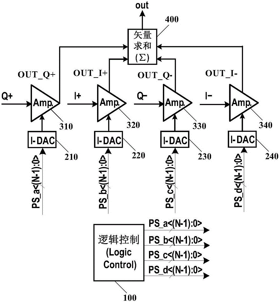
[0050] The digital phase shifter provided by the embodiment of the present application includes: a logic control circuit, at least four current digital-to-analog converters, at least four amplifiers, and a vector summation circuit.

[0051] Wherein, the logic control circuit is used to receive the N+2 digital control source signal, and generate and output four N-bit digital phase-shift control signals according to the N+2 digital control source signal; the N+2-bit Th...


PUM


Abstract

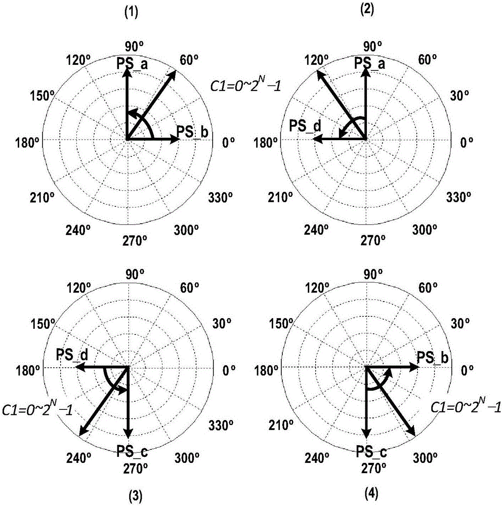
The embodiment of the invention discloses a digital phase shifter comprising a logic control circuit, at least four current digital-to-analog converters, at least four amplifiers and a vector summation circuit. The logic control circuit generates four N-bit digital phase shifting control signals according to (N+2)-bit digital control source signals to be respectively inputted to the four current digital-to-analog converters. The four current digital-to-analog converters are respectively connected in series with the four amplifiers so as to realize selection and amplification of four orthogonal input signals. The vector summation circuit synthesizes the amplification signals outputted by the four amplifiers so as to obtain the signals of which the phase can be shifted within the range of 360 degrees. The digital phase shifter is simple in circuit structure without additional arrangement of a phase shifting switching circuit so that noise can be reduced and the phase error / amplitude error can be improved; the circuit area is small and the chip cost can be reduced; and the phase shifting accuracy is high, and the accuracy value of the digital phase shifter can be adjusted by changing the total bits of the digital control source signals and the accuracy of the current digital-to-analog converters so as to meet different phase shifter design requirements.

Description

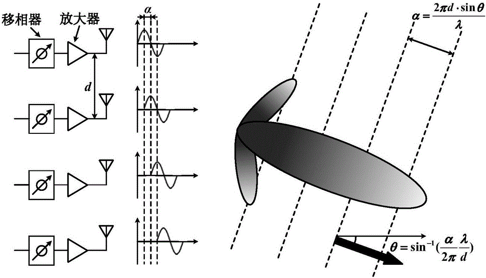
technical field [0001] The present application relates to the technical field of phase shifters, in particular to a digital phase shifter. Background technique [0002] In a wireless transceiver system, an ideal isotropic antenna transmits RF signals uniformly in all directions. However, a large amount of energy in the transmitted signal is not received by the receiving antenna, resulting in lower received signal power and greater spatial transmission power loss. Beamforming technology can solve this problem by creating directional antenna beams. Active phased array transceiver system is a kind of beamforming technology. figure 1 In the active phased array transceiver system shown, the antennas are arranged in a straight line at equal intervals (d) to form an array, and the phase difference of the input RF signals of adjacent antennas is α (that is, the delay ΔT), so the beam angle θ is determined by the following formula : [0003] Where λ is the carrier f of the tran...

Claims


Application Information

Patent Timeline
Patent Type & Authority Applications(China)
IPC IPC(8): H03H11/16
CPCH03H11/16H03H11/20H03H17/08H01P1/18H03H11/22
Inventor 钱慧珍罗讯
Owner HUAWEI TECH CO LTD
Learn More