
A heat exchanger, a charger cabinet and a charger using the heat exchanger

A technology for heat exchangers and cabinets, which is applied in the fields of heat exchangers, charger cabinets and chargers. It can solve the problems of affecting the heat exchange effect, poor heat dissipation effect, and large heat transmission distance, so as to achieve high heat transfer efficiency and improve heat dissipation. Good effect and heat exchange effect

Active Publication Date: 2019-04-30
XJ POWER CO LTD +3
View PDF9 Cites 0 Cited by
  • Summary
  • Abstract
  • Description
  • Claims
  • Application Information

AI Technical Summary

Problems solved by technology

[0005] This kind of heat pipe radiator is arranged on the top of the cabinet. Since the heat absorption area and the heat dissipation area are arranged in parallel, the lateral volume of the entire radiator is relatively large, and the installation space on the top of the general cabinet is limited. The heat absorption area and the heat dissipation area Both occupy a certain amount of installation space, so the arrangement length and quantity of heat pipes are limited, which will directly affect the heat dissipation effect of the heat pipe radiator, and for small cabinets, the heat dissipation effect will be even worse
[0006] In addition, the heat-absorbing area and the heat-dissipating area separate the shell into two parts, and the heat is transferred from the heat-absorbing area to the heat-dissipating area through the heat pipe. This heat transfer distance is relatively large, which affects the efficiency of heat transfer, thereby affecting the heat exchange effect

Method used


Image

  • A heat exchanger, a charger cabinet and a charger using the heat exchanger
  • A heat exchanger, a charger cabinet and a charger using the heat exchanger
  • A heat exchanger, a charger cabinet and a charger using the heat exchanger

Examples


Embodiment Construction

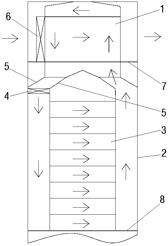
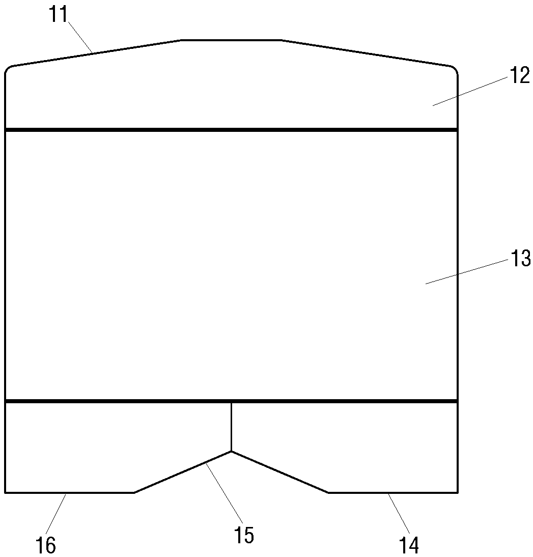
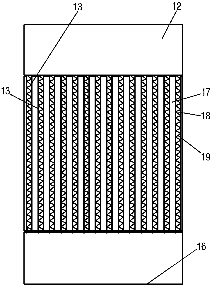
[0037] An example of a charger is Figure 1~Figure 4 As shown, it includes a cabinet 2, a charging module 3 is arranged in the cabinet 2, a heat exchanger 1 is arranged on the top of the cabinet 2, and the heat exchanger 1 includes a casing 11, and 28 cells are arranged in the casing 11 and arranged side by side at intervals along the thickness direction. The heat conduction wall 13 of the cloth, any two adjacent heat conduction walls 13 are combined to form a heat conduction channel, and the heat conduction channel is divided into a hot channel 17 and a cold channel 18, and the hot channel 17 and the cold channel 18 are arranged alternately along the arrangement direction of the heat conduction wall 13 , and there are 13 hot aisles 17 and 14 cold aisles 18.

[0038] The extension direction of the hot aisle 17 is the up-down direction, and the extension direction of the cold aisle 18 is the left-right direction. Both the hot aisle 17 and the cold aisle 18 are provided with alu...


PUM


Abstract

The invention provides a heat exchanger, a charger cabinet using the same and a charger. The heat exchanger comprises a shell; the shell is internally provided with more than three heat conduction walls arranged side by side at intervals along a thickness direction; any adjacent two heat conduction walls is joined to form a heat conduction channel; heat conduction channels are divided into heat channels and cold channels; the heat channels and the cold channels are arranged alternatively along the arrangement direction of the heat conduction walls; the heat channel is provided with a heat channel air inlet and a heat channel air outlet in sealed match with the cabinet; the cold channel is provided with a cold channel inlet and a cold channel outlet independently from the heat channel; and the heat channel air inlet and the cold channel inlet are arranged on different surfaces. Air heat in the cabinet is absorbed by the heat conduction walls, the temperature of the air exhausted from the heat channel air outlet is greatly reduced, and thus, the inner part of the cabinet can be cooled. As the cold channels and the heat channels are arranged alternatively and independent mutually, the heat exchanger has a compact structure, the occupied space is small, the heat can be quickly transferred to the cold channels from the heat channels, the heat transfer efficiency is high, and the heat exchange effects are better.

Description

technical field [0001] The invention relates to a heat exchanger, a charger cabinet and a charger using the heat exchanger. Background technique [0002] In order to reduce the environmental pollution caused by vehicle exhaust, the country vigorously advocates the development of new energy vehicles, and charging facilities are the basis for the development of new energy vehicles. Currently, in order to improve charging efficiency, the charging equipment used is mainly DC charging equipment. The charging module is the core unit of the DC charging equipment. The main function of the charging module is to perform AC / DC power conversion. During the power conversion process, some energy will be lost, and most of the lost energy will be converted into heat. The continuous accumulation of heat will cause local If the temperature is too high, the operating efficiency and life of the charging module will be seriously affected. In severe cases, the module will crash and the charging d...

Claims


Application Information

Patent Timeline
Patent Type & Authority Patents(China)
IPC IPC(8): H05K7/20B60L53/302
CPCB60L53/31H05K7/20909Y02T10/70Y02T10/7072Y02T90/12
Inventor 李建国张小广房相成高庆勇李方王晓磊王硕宣志文
Owner XJ POWER CO LTD
Learn More