Under-sill water delivery energy dissipation structure and construction method thereof

A construction method and energy dissipation technology, applied in the direction of ship lifting devices, ship locks, buildings, etc., can solve problems such as not being able to adapt to the construction requirements of ship locks, achieve the effects of solving energy and flow distribution, reducing construction difficulty, and saving engineering investment

Inactive Publication Date: 2017-05-17
POWERCHINA HUADONG ENG COPORATION LTD
View PDF5 Cites 2 Cited by
  • Summary
  • Abstract
  • Description
  • Claims
  • Application Information

AI Technical Summary

Problems solved by technology

For large-scale ship lock construction, due to different rivers and different water heads, the selection of models simply according to the norms can no longer meet the requirements of ship lock construction. For the type selection of high water head, large flow, narrow river bed, and non-standard ship lock water delivery system, it is necessary to break through the norms stipulations, research innovative achievements, in order to meet the layout and operation requirements of ship locks with different water heads at all levels

Method used


Image

  • Under-sill water delivery energy dissipation structure and construction method thereof
  • Under-sill water delivery energy dissipation structure and construction method thereof
  • Under-sill water delivery energy dissipation structure and construction method thereof

Examples


Embodiment Construction

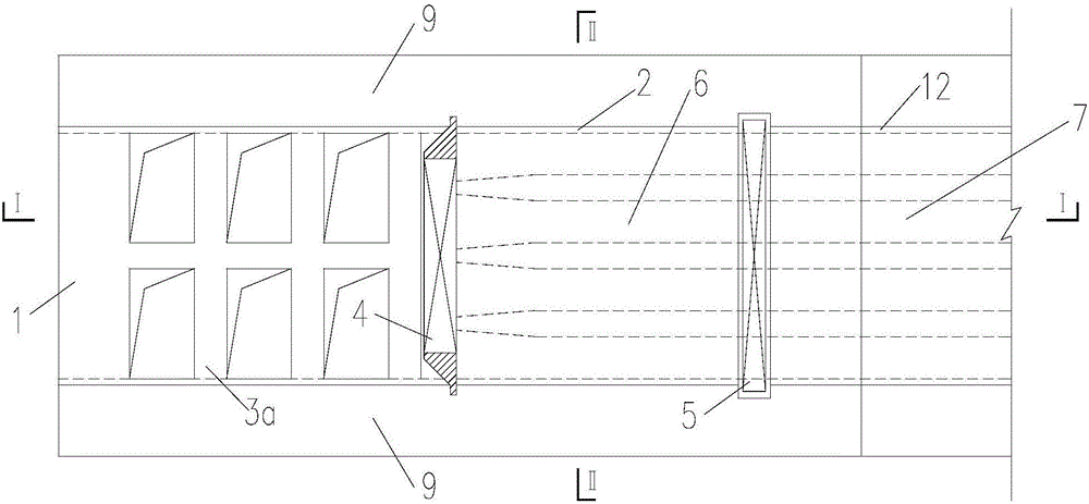
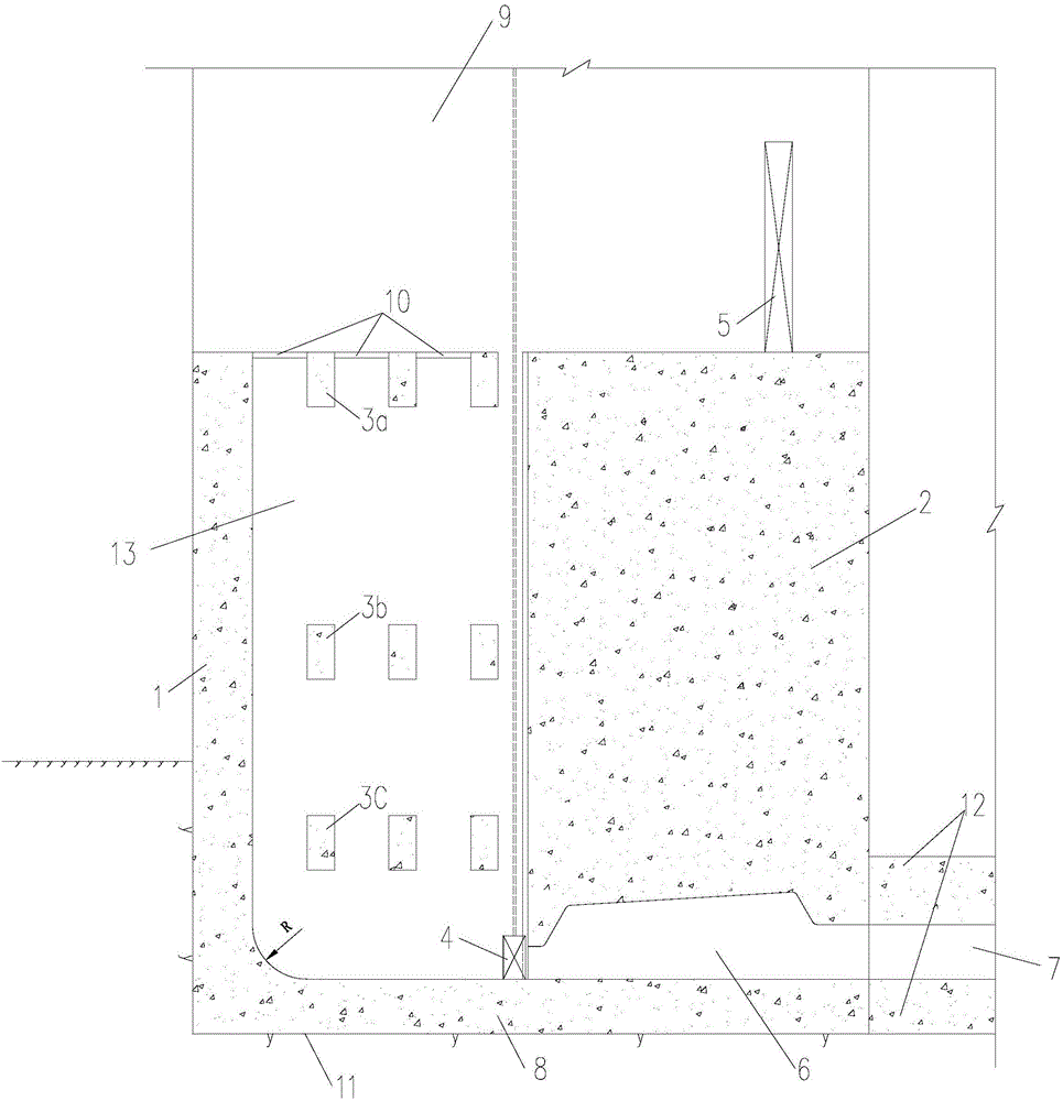
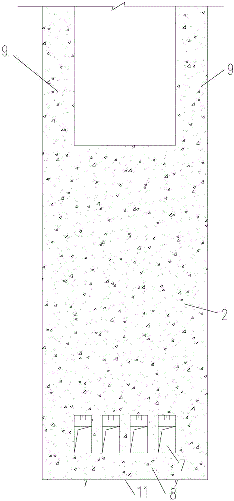
[0028] Such as Figure 1 ~ Figure 3 As shown, the present embodiment is a structure for conveying water under the sill and dissipating energy, using the space at the head of the ship lock to arrange the water retaining vertical plate 1, the energy dissipation grid, the head curtain wall 2, and the side wall 9 of the lock.

[0029] The gate head position is poured with gate head bottom plate 8, gate head curtain wall 2 is built on the gate head bottom plate 8, and gate side walls 9 are poured on both sides of gate head curtain wall 2. The water-retaining vertical plate 1, the water-retaining vertical plate 1 and the curtain wall 2 of the gate head are separated by a certain distance, so that a vertical water delivery shaft 13 is formed between the water-retaining vertical plate 1 and the curtain wall 2 of the gate head. Three layers of energy dissipation grids are provided at different elevations in the shaft 13 (the lower energy dissipation grid 3c, the middle energy dissipati...


PUM


Abstract

The invention relates to an under-sill water delivery energy dissipation structure and a construction method thereof. The invention aims at providing the under-sill water delivery energy dissipation structure which is simple in simple, convenient to construct and high in energy dissipation efficiency and the construction method of the under-sill water delivery energy dissipation structure. According to the technical scheme, the under-sill water delivery energy dissipation structure is provided with a lock head bottom plate, a lock head curtain wall and lock side walls, wherein the lock head curtain wall is poured onto the lock head bottom plate, and the lock side walls are on the two sides of the lock head curtain wall. The under-sill water delivery energy dissipation structure is characterized in that a water retaining vertical plate is built in the position, a certain distance spaced from the lock head curtain wall, of the lock head bottom plate on the upstream side of the lock head curtain wall; a perpendicular water delivery vertical well is formed between the water retaining vertical plate and the lock head curtain wall; energy dissipation devices are arranged in the perpendicular water delivery vertical well; the lower portion of the perpendicular water delivery vertical well communicates with water inlets of a plurality of sudden expansion chambers reserved at the bottom of the lock head curtain wall; and water outlets of the sudden expansion chambers communicate with a ship lock chamber through a water delivery gallery reserved in a lock bottom plate on the downstream side of the lock head curtain wall. The under-sill water delivery energy dissipation structure and the construction method thereof are suitable for water conservancy and hydropower engineering and water transportation traffic engineering.

Description

technical field [0001] The invention relates to an under-sill water conveyance and energy dissipation structure and a construction method thereof. Applicable to water conservancy and hydropower projects, water transportation and transportation projects. Background technique [0002] The development of navigable structures has a history of more than 2,000 years, and nearly 4,000 ship locks have been built around the world. The history of ship lock construction in my country is very long, and nearly 800 ship locks have been built so far, accounting for about 20% of the total number of ship locks in the world. In the design of the ship lock, the type selection of the water delivery system and the advantages and disadvantages of the energy dissipation structure type are one of the most critical technologies to ensure the efficient and safe operation of the ship lock. According to the current regulations of my country's transportation industry, there are mainly two types of wat...

Claims


Application Information

Patent Timeline
Patent Type & Authority Applications(China)
IPC IPC(8): E02C1/08
CPCE02C1/08
Inventor 扈晓雯郑永明姚实
Owner POWERCHINA HUADONG ENG COPORATION LTD
Why Eureka
Try Eureka