Simple and rapid anchoring method and apparatus of distributive sensing optical cable

A technology for sensing optical cables and anchoring devices, which is applied in the direction of using optical devices, measuring devices, and converting sensor output, etc., can solve problems such as reducing the accuracy of optical fiber monitoring data, large and micro-bend losses in optical paths, and affecting construction progress, etc., reaching a broad market Promote and apply the value, reduce stress concentration, and improve the effect of construction efficiency

Pending Publication Date: 2017-05-17
NANJING UNIV
View PDF8 Cites 4 Cited by
  • Summary
  • Abstract
  • Description
  • Claims
  • Application Information

AI Technical Summary

Problems solved by technology

The method of glue fixing is relatively complicated to operate, and it needs to wait for the glue to solidify during implementation, which affects the construction progress and has great limitations in terms of poor installation standardization, time-consuming construction, and aesthetics; on the other hand, in long-term monitoring During the process, the performance of the glue is affected by environmental factors such as temperature, humidity, and air dust. There are many shortcomings such as unreliable fixation, poor coupling of deformation, poor durability, and easy aging and falling off.
[0005] Simple physical anchoring generally uses iron wire binding, or screws, nuts, and rigid clips to fix, etc. The former has the disadvantages of simple anchoring methods and easy slippage of optical cables, while the latter has many construction steps, and the special clip structure is complex and expensive. Disadvantages such as controlling the size of the clamping force
Another important problem is that simple physical anchoring can neither fully meet the anchoring strength requirements, but also cause potential physical damage to the optical cable structure, and large microbending losses are prone to occur on the optical path, reducing the accuracy of optical fiber monitoring data. , in severe cases, monitoring readings cannot be obtained

Method used


Image

  • Simple and rapid anchoring method and apparatus of distributive sensing optical cable
  • Simple and rapid anchoring method and apparatus of distributive sensing optical cable
  • Simple and rapid anchoring method and apparatus of distributive sensing optical cable

Examples


Embodiment

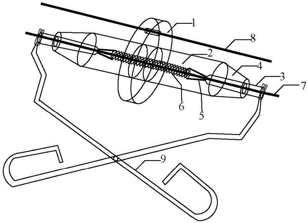
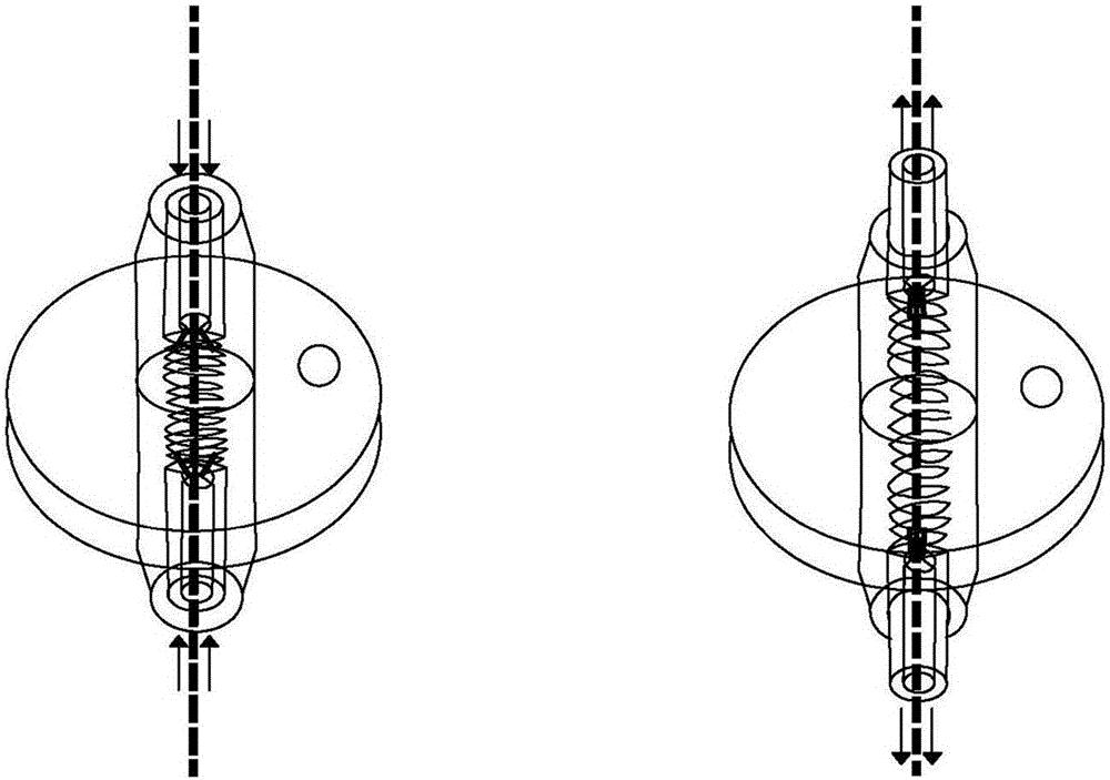
[0030] like figure 1 and figure 2As shown, the structure of the present invention includes: a flange 1, a large cylinder 2, a small cylinder 3, a hollow round table 4, a metal clip 5, and a spring 6. The main structure includes a flange plate and a large cylinder welded to each other, and a hollow round table is fixed at both ends. A spring is arranged in the large cylinder, metal clips are fixed at both ends of the spring, and the other end of the metal clip is connected with the small cylinder. The metal clip is flat and long, and a layer of rubber gasket is attached on the surface of the metal sheet, so that there will be no stress concentration when anchoring the optical fiber or cable. The flange, the large cylinder, the spring, the metal clip and the small cylinder are coaxial; the optical cable installation clips are detachably connected to the small cylinders at both ends.

[0031] When the small cylinders at both ends of the anchoring device are pressed into the l...


PUM


Abstract

The invention discloses a simple and rapid anchoring method and apparatus of a distributive sensing optical cable. A large cylinder is nested in a flange, and hollow circular truncated cones are fixed at two ends of the large cylinder; a spring is arranged in the large cylinder, metal clamping pieces are fixed at two ends of the spring, the other end of each metal clamping piece is connected with a small cylinder, and the flange, the large cylinder, the spring, the metal clamping pieces and the small cylinder are coaxial; and a loose-sleeve distributive sensing optical cable passes through a circular hole on the peripheral edge of the flange to play an effect of temperature compensation and alignment. According to the optical cable anchoring apparatus, the elastic force is controlled by virtue of a stiffness coefficient of the spring, the stress on a cross section of the loose-sleeve distributive sensing optical cable is uniformly distributed, and the optical cable is firmly installed; and moreover, the simple and rapid anchoring apparatus is small in size, simple in production, easy to operate, rapid to install, low in cost, small in micro-bend loss of an optical path, reliable in anchoring effect, suitable for the distributive sensing cables of different sizes, structures and cladding materials, and can firmly fix the distributive sensing optical cable on concrete, inside a rock and earth mass or on the surfaces of steel structures and concrete structures.

Description

technical field [0001] The invention relates to the field of optical fiber monitoring and laying technology, in particular to a simple and fast anchoring method and device for a distributed sensing optical cable. Background technique [0002] As a new type of sensing technology, optical fiber sensing technology has developed rapidly in recent decades, with high sensitivity, small size, strong anti-interference, good insulation, corrosion resistance, high cost performance, long monitoring distance, easy integration, etc. advantage. Among them, Brillouin Optical Time Domain Reflectometry (BOTDR), Brillouin Optical Time Domain Analysis (BOTDA), Brillouin Optical Frequency Domain Analysis (BOFDA) and other distributed optical fiber sensing technologies will "transmit" and "sense "Integrated two into one, it can measure parameters such as strain and temperature at all positions along the optical fiber and optical cable. , Geological disaster monitoring and early warning has gre...

Claims


Application Information

Patent Timeline
Patent Type & Authority Applications(China)
IPC IPC(8): G01D5/26G01B11/16
CPCG01B11/16G01D5/268
Inventor 朱鸿鹄李飞施斌张诚成
Owner NANJING UNIV
Why Eureka
Try Eureka