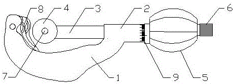
Transverse defect verification method in eddy current testing and pipe cutting device with vernier adjustment knob

An eddy current flaw detection and lateral defect technology, applied in the direction of material magnetic variables, etc., can solve the problems affecting the accuracy of eddy current monitor sensitivity calibration, lack of flexibility, inconvenient calibration, etc., to achieve controllable verification frequency, increase smoothness, use Flexible and convenient effects

Inactive Publication Date: 2017-05-17
BAOSTEEL GRP NANTONG WIRE PROD
View PDF6 Cites 2 Cited by
  • Summary
  • Abstract
  • Description
  • Claims
  • Application Information

AI Technical Summary

Problems solved by technology

[0003] Chinese Patent No. CN94112216.6 discloses a method for adjusting roll eddy current monitoring equipment. The system is composed of artificial damage test block, artificial damage signal simulation generator, and computer eddy current detection equipment. The artificial damage test block is used to replace the sample roll. The computer eddy current flaw detection equipment calibrates the artificial flaw test block to obtain a vector, and then puts the probe of the computer eddy current flaw detection equipment on the artificial flaw signal simulation generator probe to obtain a vector similar to the above vector, and the artificial flaw signal simulation generator probe Place it under the probe of the roll eddy current monitor, adjust the gain of the roll eddy current monitor and the envelope frequency of the artificial injury signal simulation generator, so that the crack or hardness difference channel o

Method used


Image

  • Transverse defect verification method in eddy current testing and pipe cutting device with vernier adjustment knob

Examples


Example Embodiment

[0031] Example 1

[0032] The method for verifying lateral defects of eddy current flaw detection specifically includes the following steps:

[0033] (1) The eddy current inspection line includes pay-off machine, straightener, shot blasting machine, eddy current inspection equipment, automatic painting equipment and drawing equipment along the direction of steel wire advance; the steel wire in production is pulled by the drawing equipment Travel along the direction from the pay-off machine to the drawing equipment; the eddy current flaw detection equipment includes a pass-through flaw detection module and a rotary flaw detection module, the pass-through flaw detection module is provided with a detection coil; the eddy current flaw detection equipment detects transverse defects on the steel wire passing through the detection coil detection;

[0034] (2) Select the steel wire surface at the front end of the eddy current flaw detection equipment and 1-2m away from the detection co...


PUM


Abstract

The invention discloses a transverse defect verification method in eddy current testing, comprising the following steps: adopting an eddy current testing detection flow line; determining the position of a flaw on a steel wire; determining the initial scale of a flaw of the pipe cutting device with the vernier adjustment knob; determining the depth of the flaw on the steel wire; determining the length of the flaw on the steel wire; starting a drawing device for drawing the steel wire, and starting a flaw detection device to carry out flaw detection; if the flaw detection device can detect the flaw position and alarm for stoppage, proving that the flaw detection device satisfies requirements on sensitivity; and if the flaw detection device cannot detect the flaw position, proving that the flaw detection device is insufficient in sensitivity and needs repair. The transverse defect verification method adopts an on-line flaw cutting and on-line verification scheme, the flaw is cut with the pipe cutting device during the production process of the steel wire, the length and depth of the flaw are determined, then a detector is used for detecting the flaw for verifying the sensitivity of the detector, and the method is quick, high in accuracy, lower in cost and flexible and convenient in use due to controllable verification frequency and controllable defect size.

Description

technical field [0001] The invention relates to the technical field of eddy current flaw detection, in particular to a method for verifying transverse defects in eddy current flaw detection and a pipe cutting device with a fine-tuning knob. Background technique [0002] With the continuous improvement of steel wire strength requirements, the surface quality of steel wire is becoming more and more important. The defects near the surface of steel wire need to be detected and ground by eddy current flaw detection to ensure the surface quality of steel wire; when performing flaw detection inspection, the sensitivity of flaw detection equipment is even higher. The most important influencing factors of inspection accuracy; how to carry out defect verification with low cost, controllable verification frequency and controllable defect size; how to realize fast, convenient and effective calibration of the sensitivity of flaw detection equipment is the current steel wire quality inspec...

Claims


Application Information

Patent Timeline
IPC IPC(8): G01N27/90
CPCG01N27/90
Inventor 王海洋李龙朱从宣朱兵张大虎周荣梅
Owner BAOSTEEL GRP NANTONG WIRE PROD
Why Eureka
Try Eureka