
Efficient pipe cleaner

A cleaning machine and pipe material technology, which is applied in the direction of dryers, cleaning hollow objects, cleaning methods and appliances, etc., can solve the problems of ineffective cleaning of the surface of stainless steel pipes, complex structure of cleaning equipment, and non-recyclable washing liquid, etc., to achieve cleaning The effect is thorough, the structure is simple, and the design is reasonable

Inactive Publication Date: 2017-05-24
天津俊海科技有限公司
View PDF0 Cites 10 Cited by
  • Summary
  • Abstract
  • Description
  • Claims
  • Application Information

AI Technical Summary

Problems solved by technology

[0002] The surface of metal products often needs to be cleaned during the production process. Metal stainless steel pipes are widely used in construction engineering, automobile manufacturing, bridge engineering and other fields. The surface of stainless steel pipes needs to be cleaned before coating. The structure of the cleaning equipment in the prior art is complicated. Since the surface of the stainless steel pipe is a curved surface structure, the cleaning is often not thorough, and the surface of the stainless steel pipe cannot be effectively cleaned.
In addition, the cleaning waste liquid of metal products usually contains a large amount of iron filings and other impurities. The direct discharge of the cleaning waste liquid is not conducive to environmental protection requirements and increases the cost of environmental protection. At the same time, the washing liquid cannot be recycled, resulting in waste

Method used


Image

  • Efficient pipe cleaner

Examples


Embodiment Construction

[0016] It should be noted that, in the case of no conflict, the embodiments of the present invention and the features in the embodiments can be combined with each other.

[0017] In describing the present invention, it should be understood that the terms "center", "longitudinal", "transverse", "upper", "lower", "front", "rear", "left", "right", " The orientations or positional relationships indicated by "vertical", "horizontal", "top", "bottom", "inner" and "outer" are based on the orientations or positional relationships shown in the drawings, and are only for the convenience of describing the present invention and Simplified descriptions, rather than indicating or implying that the device or element referred to must have a particular orientation, be constructed and operate in a particular orientation, and thus should not be construed as limiting the invention. In addition, the terms "first", "second", etc. are used for descriptive purposes only, and should not be understood ...


PUM


Abstract

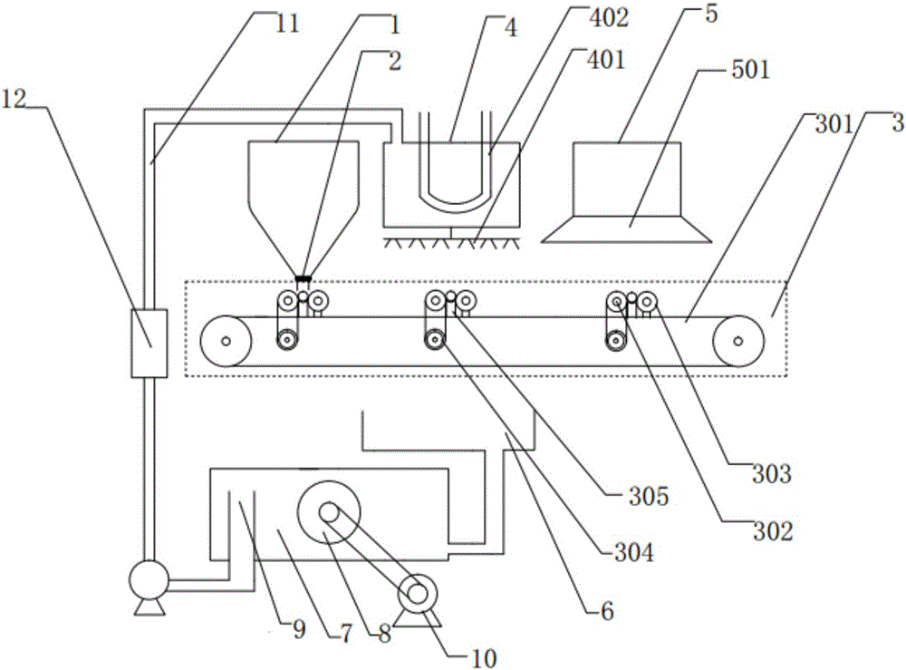
The invention provides an efficient pipe cleaner which comprises a steel pipe storage hopper, a transmission unit, a leaching unit, a blow-drying unit and a washing liquor circulating and demagnetizing unit, wherein a pipe outlet adaptive to a stainless steel pipe is formed in the bottom of the steel pipe storage hopper; an elastic plate connected with a controller is arranged in the pipe outlet; stainless steel pipe fixing slots are distributed in the surface of a conveyor belt at equal distance; the outer surface of a drive roller and the outer surface of a driven roller are rotatably connected with the stainless steel pipe; the leaching unit and the blow-drying unit are arranged above the transmission unit in parallel in sequence; the washing liquor circulating and demagnetizing unit comprises a water collecting slot, a demagnetizing box, a magnetic rotary disc and a liquor outlet pipe; and the liquor outlet pipe is vertically arranged at the left side in the demagnetizing box. The efficient pipe cleaner is relatively high in degree of automation; a pipe fixing slot is formed in the surface of the conveyor belt, so that the stainless steel pipe can be kept to rotate in a conveying process, and therefore, the cleaning effect is more complete. The demagnetizing box can recycle washing liquor, so that production cost is reduced.

Description

technical field [0001] The invention belongs to the technical equipment field of cleaning stainless steel pipes, and in particular relates to a high-efficiency pipe cleaning machine. Background technique [0002] The surface of metal products often needs to be cleaned during the production process. Metal stainless steel pipes are widely used in construction engineering, automobile manufacturing, bridge engineering and other fields. The surface of stainless steel pipes needs to be cleaned before coating. processing, the cleaning equipment in the prior art has a complex structure, and because the surface of the stainless steel pipe is a curved surface structure, the cleaning is often not thorough, and the surface of the stainless steel pipe cannot be effectively cleaned. In addition, the cleaning waste liquid of metal products usually contains a large amount of iron filings and other impurities. The direct discharge of the cleaning waste liquid is not conducive to environmenta...

Claims


Application Information

Patent Timeline
IPC IPC(8): B08B9/023B08B3/02B08B3/14B03C1/02B08B13/00F26B21/00
CPCB08B9/023B03C1/02B08B3/022B08B3/14B08B13/00F26B21/00
Inventor 崔海洋
Owner 天津俊海科技有限公司
Learn More