Fuel tank cap with carbon tank function

A fuel tank cap and function technology, which is applied to the charging system, adding non-fuel substances to fuel, machinery/engine, etc. effect of path

Active Publication Date: 2017-05-24
宁波利凯特环保科技有限公司
View PDF6 Cites 3 Cited by
  • Summary
  • Abstract
  • Description
  • Claims
  • Application Information

AI Technical Summary

Problems solved by technology

However, its disadvantages are: the carbon canister and fuel tank are separated, in other words, the carbon canister is installed outside the fuel tank, and the carbon canister is connected to the fuel tank th...

Method used


Image

  • Fuel tank cap with carbon tank function
  • Fuel tank cap with carbon tank function
  • Fuel tank cap with carbon tank function

Examples


Embodiment Construction

[0026] The present invention will be described in further detail below in conjunction with the accompanying drawings and specific embodiments.

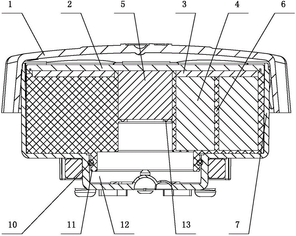
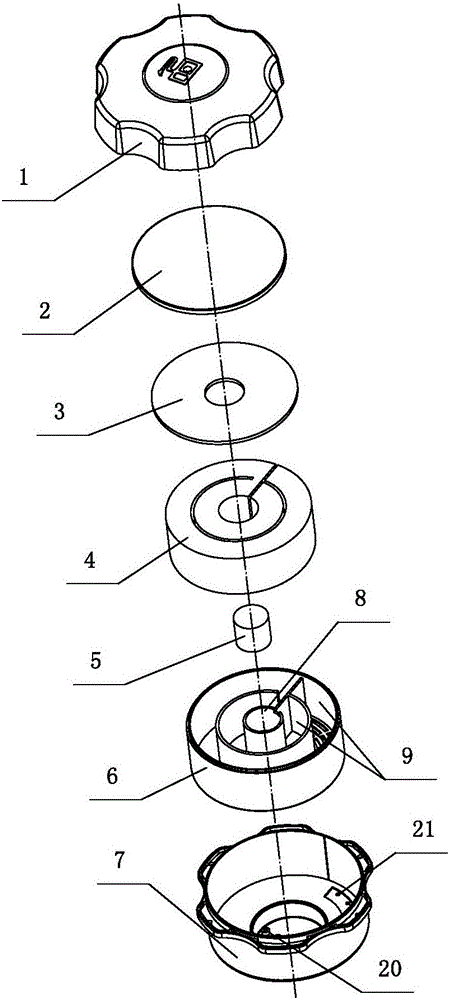
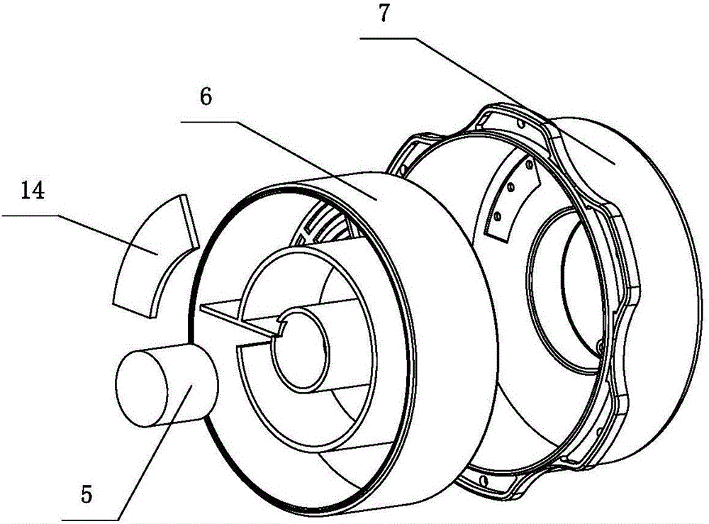
[0027] Depend on Figure 1 to Figure 5 As can be seen from the structural schematic diagram of the fuel tank cap with carbon canister function shown in the present invention, it includes an upper cover 1, a tank body 7 and carbon powder 4, and the carbon powder 4 is filled in the tank body 7, and the tank body 7 is connected with the upper cover 1 . It also includes a support frame 6 for accommodating the toner 4 , the support frame 6 is sleeved in the tank body 7 , and the lower end of the support frame 6 is sealed with the tank body 7 . The support frame 6 has a central pipe column 8 and a continuous channel 9 for extending the oil vapor flow path. The starting end of the continuous channel 9 communicates with the central pipe column 8, and the terminal communicates with the outside of the fuel tank. The bottom of the tank body 7 ...


PUM


Abstract

The invention discloses a fuel tank cap with the carbon tank function. The fuel tank cap comprises an upper cap body (1), a tank body (7), carbon dust (4) and a supporting frame (6) used for containing the carbon dust (4). The supporting frame (6) is connected into the tank body (7) in a sleeved mode. The lower end of the supporting frame (6) is connected with the tank body (7) in a sealing mode. The supporting frame (6) is provided with a center tube pillar (8) and a continuous channel (9) used for lengthening an oil vapor circulating path. The starting end of the continuous channel (9) communicates with the center tube pillar (8), and the stop end of the continuous channel (9) communicates with the outside of a fuel tank. A first air hole (20) communicating with a fuel tank inner cavity and a second air hole (21) communicating with the outside of the fuel tank are formed in the bottom of the tank body (7). The first air hole (20) communicates with the center tube pillar (8), and the second air hole (21) communicates with the stop end of the continuous channel (9). By the adoption of the structure, the fuel tank cap is more compact in structure and is more suitable for small-sized mechanical equipment; and moreover, the circulating path of fuel oil steam is greatly prolonged, and adsorption efficiency is made higher.

Description

technical field [0001] The invention relates to an oil tank cap with the function of a carbon tank. Background technique [0002] Usually, a carbon tank is installed between the gasoline tank and the engine, because activated carbon has an adsorption function. When the car is running or turned off, the fuel vapor in the fuel tank enters the upper part of the activated carbon tank through the pipeline, and the fresh air flows from the activated carbon tank. The lower part enters the activated carbon tank. After the engine is turned off, gasoline vapor and fresh air are mixed in the tank and stored in the activated carbon tank. When the engine is started, the solenoid valve of the fuel evaporation purification device installed between the activated carbon tank and the intake manifold opens, and the activated carbon tank Gasoline vapors are drawn into the intake manifold for combustion. In the prior art, the carbon canister and the fuel tank are generally installed separately...

Claims


Application Information

Patent Timeline
IPC IPC(8): F02M37/00F02M25/08
CPCF02M25/08F02M37/0076
Inventor 葛中华
Owner 宁波利凯特环保科技有限公司
Why Eureka
Try Eureka