Main clutch electrically controlled hydraulic operation mechanism for harvester

A main clutch and electronically controlled hydraulic technology, which is applied to clutches, harvesters, agricultural machinery and implements, etc., can solve problems such as laborious operation and complicated transmission, and achieve the effects of avoiding potential safety hazards, simplifying connection parts, and simplifying the operation of the whole machine

Active Publication Date: 2017-05-24
LUOYANG FERGUSON MECHANICAL EQUIP
View PDF5 Cites 3 Cited by
  • Summary
  • Abstract
  • Description
  • Claims
  • Application Information

AI Technical Summary

Problems solved by technology

[0003] In order to overcome the problems of complex transmission and laborious operation of the main clutch control mechanism of the existing harvester, the present invention provides a main clutch control mechanism with simple structure and labor-saving operation, which controls the main clutch through electro-hydraulic control

Method used


Image

  • Main clutch electrically controlled hydraulic operation mechanism for harvester
  • Main clutch electrically controlled hydraulic operation mechanism for harvester
  • Main clutch electrically controlled hydraulic operation mechanism for harvester

Examples


Embodiment Construction

[0017] Below in conjunction with the accompanying drawings, the technical solution of the present invention will be further described through specific implementation methods, so that those skilled in the art can better understand the present invention and implement it, but the examples given are not intended to limit the present invention .

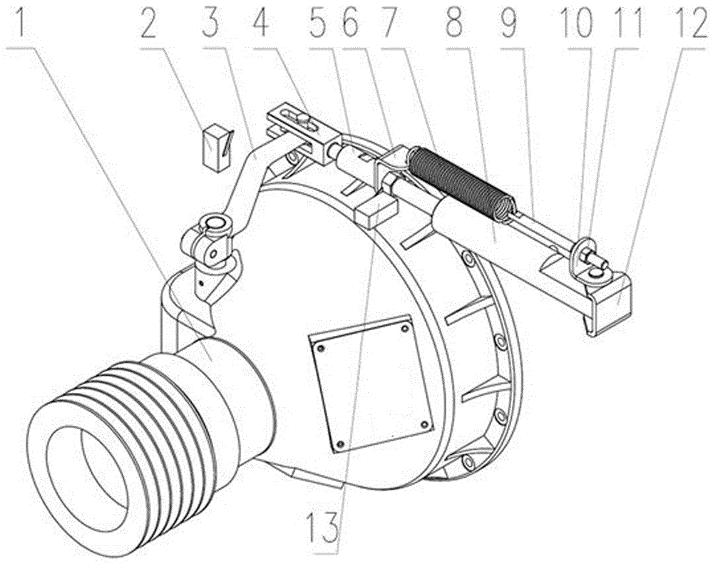
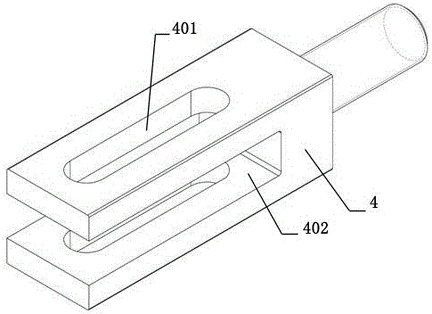
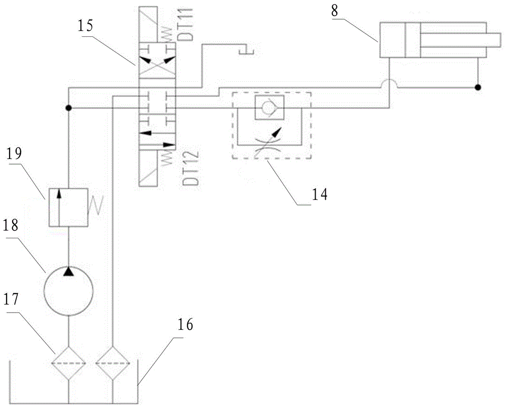
[0018] As shown in the figure, a main clutch electro-hydraulic control mechanism for a harvester includes a main clutch 1, which is connected to the power output end of the engine and controls the combination and separation of the main clutch 1 through a rotating arm 3; it also includes a control main clutch 1. The mechanical part, the electric control part and the hydraulic part of the coupling and separation of the clutch 1; the mechanical part includes the arm connecting fork 4, the connecting sleeve 5, the extension spring 7, the extension spring seat, the adjusting screw 9 and the cylinder seat 12; the electric control part includes t...


PUM


Abstract

The invention discloses a main clutch electrically controlled hydraulic operation mechanism for a harvester. The main clutch electrically controlled hydraulic operation mechanism comprises a main clutch, wherein a rotating arm which realizes combination and separation of the main clutch is connected with a piston of a main clutch oil cylinder through a connection device; the connection device comprises a rotating arm connection fork and a middle connection piece which are connected with each other; an opening in which the rotating arm is inserted is formed in a fork head at one end of the rotating arm connection fork, and opposite long holes are respectively formed in side plates on two sides of the opening; the end part of the rotating arm can move in the long holes through pin shafts; a tension spring is arranged on the main clutch oil cylinder; two ends of the tension spring are respectively connected with a cylinder body and the piston of the main clutch oil cylinder; a combination electrical control switch and a separation electrical control switch are respectively arranged at two ends of the rotating arm in a rotating travel; an electrical control button is arranged in a cab; the electrical control button is connected with an electromagnetic reversing valve in a hydraulic control loop for controlling the main clutch oil cylinder; a uni-directional throttling valve is arranged between the electromagnetic reversing valve and the main clutch oil cylinder. The main clutch electrically controlled hydraulic operation mechanism for the harvester simplifies connection pieces of the whole machine, improves the part reliability and greatly reduces the labor intensity of a driver.

Description

technical field [0001] The invention relates to the technical field of agricultural machinery, in particular to an electronically controlled hydraulic control mechanism for a main clutch of a harvester. Background technique [0002] At present, the main clutch assembly has been widely used in power output devices on harvesters in my country. The main clutch assembly is connected to the harvester engine and controls the coupling or separation of the clutch by manipulating the rotation of the rotating arm. There is a self-locking point in the rotation stroke of the clutch arm. After turning over the self-locking point, there is no need to operate, and the arm will automatically turn forward and then a certain angle. At this time, the friction plate has been compressed and the clutch is in the combined position; pull back After moving the rotating arm, after passing the self-locking point, the rotating arm will automatically bounce off, the friction plate is released, and the c...

Claims


Application Information

Patent Timeline
Patent Type & Authority Applications(China)
IPC IPC(8): F16D48/06A01D69/08
CPCA01D69/08F16D48/066
Inventor 鲁正宏魏志松刘厚贤宋华梁晓剑赵井旭李广文郭培龙焦轶冰
Owner LUOYANG FERGUSON MECHANICAL EQUIP
Why Eureka
Try Eureka