Automatic analysis device and sample analysis method

An automatic analysis device, a technology for sample analysis, applied in the direction of analysis materials, instruments, etc., can solve the problems of increasing materials, processing, production costs and overall machine size, large disc or manifold size, and complicated incubation measurement unit control. , to achieve the effect of improving test efficiency, flexible incubation time, and reducing the burden of test subjects

Active Publication Date: 2017-05-24
SHENZHEN LINKRAY BIOTECH CO LTD
View PDF4 Cites 15 Cited by
  • Summary
  • Abstract
  • Description
  • Claims
  • Application Information

AI Technical Summary

Problems solved by technology

In addition, in order to achieve flexible incubation time in this technical solution, the control of the incubation measurement unit is complicated, and the control of incubation and measurement will also restrict each other, making it difficult to realize high-speed automated testing
[0011] The third prior art solution realizes incubation, cleaning, separation and measurement on a single-circle disc or divergent track. In order to support longer incubation time, in addition to cleaning, separating and measuring positions, the disk also needs to set a lot of incubation positions, so in order to achieve high-speed testing, the size of the disk or divergent track needs to be designed to be large, which is difficult to manufacture and high in cost. In addition, in order to To realize delayed one-step and two-step testing, at least two sample loading mechanisms and at least two cleaning and separation mechanisms are required, which increases the cost of materials, processing, production and overall machine size
On the other hand, this technical solution also limits the incubation time, leading to problems such as fixed incubation time and too long time to produce results.

Method used


Image

  • Automatic analysis device and sample analysis method
  • Automatic analysis device and sample analysis method
  • Automatic analysis device and sample analysis method

Examples


Embodiment Construction

[0033] The present invention will be further described in detail below through specific embodiments in conjunction with the accompanying drawings.

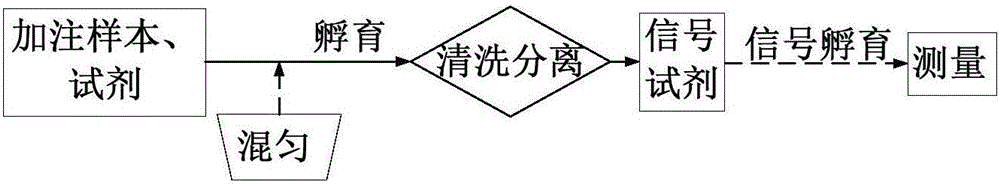
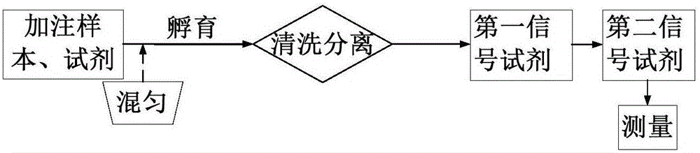
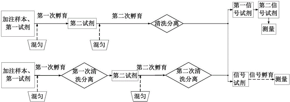
[0034] An automatic analysis device for measuring target analytes in samples according to the present invention, comprising: a filling unit, which injects samples or / and reagents into a reaction vessel, a reaction unit, incubates the reactants in the reaction vessel and transfers them to the reaction vessel, cleans and separates The unit cleans and separates the reactants in the reaction vessel, and the measurement unit measures the reaction signal in the reaction vessel. The reaction unit includes a rotating device, and the reaction vessel position is set on the rotating device for carrying and fixing the reaction vessel; The reaction vessel position comprises a first reaction vessel position and a second reaction vessel position, the first reaction vessel position transfers the reaction vessel to the cleaning separation unit or / a...


PUM


Abstract

The invention provides an automatic analysis device and a sample analysis method. The automatic analysis device comprises a filling unit (20), a reaction unit (10), a cleaning and separating unit (2) and a measurement unit (1), wherein the filling unit (20) is used for filling a sample or/and reagent into a reaction vessel; the reaction unit (10) is used for incubating reactants in the reaction vessel and transferring the reaction vessel; the cleaning and separating unit (2) is used for cleaning and separating the reactants in the reaction vessel; the measurement unit (1) is used for measuring a reaction signal in the reaction vessel; the reaction unit (10) comprises a rotary device (11); and a reaction vessel position is arranged on the rotary device (11) and used for bearing and fixing the reaction vessel. In the invention, the incubation, cleaning and separating and measurement of the reactants in the reaction vessel are realized by taking the reaction unit as a center, so that a cleaning and separating disc and a measurement disc are saved, the system structure and control flow are simplified, the size of the reaction unit can be remarkably reduced, flexible incubation time is realized, and the working efficiency of the analysis device is improved.

Description

technical field [0001] The invention relates to the field of in vitro diagnostic equipment, in particular to an automatic analysis device and a sample analysis method. Background technique [0002] In recent years, the development and progress of clinical testing and automation technology has not only improved the level of clinical laboratory automation, improved the efficiency of medical testing, but also improved the quality and reliability of test results. However, as the amount of test specimens increases, clinical laboratories need to continuously add large-scale automated testing systems to meet their testing needs, resulting in increasingly crowded laboratories and rising testing costs. Therefore, under the pressure and challenge of medical insurance cost control, how to improve the efficiency of testing, guarantee the results, make full use of existing laboratory resources and reduce testing costs is an urgent problem to be solved in clinical testing. [0003] For t...

Claims


Application Information

Patent Timeline
Patent Type & Authority Applications(China)
IPC IPC(8): G01N35/02
CPCG01N35/02G01N35/0092G01N35/0098G01N2035/00356G01N35/025G01N2035/0444G01N2035/00326G01N35/04G01N2035/0441
Inventor 刘丹
Owner SHENZHEN LINKRAY BIOTECH CO LTD
Why Eureka
Try Eureka