High-precision positioning device and method for far focus of ellipsoidal reflector

A technology of ellipsoidal reflector and positioning device, which is applied in the direction of condenser, instrument, optics, etc., and can solve the problems of extremely high accuracy of installation and adjustment, large coma aberration and astigmatism

Active Publication Date: 2017-05-24
HARBIN INST OF TECH
View PDF7 Cites 1 Cited by
  • Summary
  • Abstract
  • Description
  • Claims
  • Application Information

AI Technical Summary

Problems solved by technology

[0003] However, since the collection aperture angle of the ellipsoidal reflector is very large, it requires extremely high adjustment accuracy. When the point source and the far focus of the ellipsoidal reflector deviate slightly in the radial direction, it will cause large coma aberration and Astigmatism, therefore, in order to take advantage of the large numerical aperture and strong contrast of the ellipsoidal reflector, it is necessary to fine-tune the ellipsoidal reflector

Method used


Image

  • High-precision positioning device and method for far focus of ellipsoidal reflector

Examples


specific Embodiment 1

[0026] This embodiment is an embodiment of a high-precision positioning device for a far focus of an ellipsoid reflector.

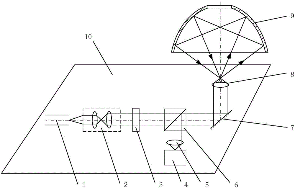
[0027] The structure diagram of the high-precision positioning device for the far focus of the ellipsoid mirror in this embodiment is as follows: figure 1 shown. The ellipsoidal mirror far-focus high-precision positioning device includes a laser 1, a collimating beam expander 2, an attenuator 3, an image sensor 4, a tube mirror 5, a beam splitter 6, a plane mirror 7 and a focusing objective lens 8. The optical path also includes an ellipsoid reflector 9; the overlapping optical path is placed on the six-degree-of-freedom workbench 10, the plane reflector 7 and the six-degree-of-freedom workbench 10 form a 45-degree angle, and the ellipsoid reflector 9 is alone Fixed on the top of the focusing objective lens 8, the focus of the focusing objective lens 8 coincides with the far focus of the elliptical cross-section of the ellipsoid reflector 9; After atten...

specific Embodiment 2

[0029] This embodiment is an embodiment of the high-precision positioning method for the far focus of the ellipsoid reflector.

[0030] The high-precision positioning method for the far focus of the ellipsoid reflector in this embodiment is implemented on the high-precision positioning device for the far focus of the ellipsoid reflector described in the first embodiment.

[0031] The high-precision positioning method for the far focus of the ellipsoid reflector includes the following steps:

[0032] Step a, turn on the laser 1, and attenuate the intensity of the parallel light beam emitted from the collimating beam expander 2 with an attenuating sheet 3, so that the image sensor 4 can effectively image;

[0033] Step b, continuously adjust the six-degree-of-freedom workbench 10 to obtain the intensity information and circularity information of the light spot collected by the image sensor 4 under different degrees of freedom;

[0034] Step c, combine the intensity information ...

specific Embodiment 3

[0038] This embodiment is an embodiment of the high-precision positioning method for the far focus of the ellipsoid reflector.

[0039] In the method for high-precision positioning of the far focus of the ellipsoid mirror in this embodiment, on the basis of the specific embodiment 2, step b is further limited as follows: the six degrees of freedom are respectively set as N1, N2, N3, N4, N5, N6 discrete numerical values ​​are arranged and combined to obtain N1×N2×N3×N4×N5×N6 kinds of combinations. Under each combination, the intensity information and circularity information of the light spot are obtained.

[0040] This embodiment provides a specific technical means for how to obtain a series of intensity information and roundness information.


PUM


Abstract

The invention discloses a high-precision positioning device and a high-precision positioning method for a far focus of an ellipsoidal reflector. The high-precision positioning device and the high-precision positioning method belong to the field of optical confocal microscopic technologies and optical precise measurement. The high-precision positioning device comprises a lapping optical path which is composed of optical elements such as laser devices, and further comprises an ellipsoidal reflector and the like. The high-precision positioning method comprises the steps of firstly, conducting effective imaging by means of an image sensor, then adjusting a six-degree-of-freedom workbench, acquiring a series of intensity information and roundness information of a light spot, merging the information into an evaluation function, establishing a degree-of-freedom and evaluation function table, finding out an extreme value of the evaluation function and a degree of freedom corresponding to the extreme value in the degree-of-freedom and evaluation function table, and finally adjusting the six-degree-of-freedom workbench according to the degree of freedom corresponding to the extreme value such that a focus of a focusing objective lens coincides with the far focus of the ellipsoidal reflector. The high-precision positioning device and the high-precision positioning method fully utilize the special property of the bifocal conjugation of the ellipsoidal reflector, and realize precise positioning of the ellipsoidal reflector through providing a technological means for positioning the far focus of the ellipsoidal reflector by utilizing the imaging light spot information.

Description

technical field [0001] The device and method for high-precision positioning of an ellipsoid surface mirror far-focus in the invention belong to the technical field of optical confocal microscopy and the field of optical precision measurement. Background technique [0002] With the development of microscopy technology, more and more attention has been paid to reflection microscopy imaging systems. The structures that can realize imaging at a large numerical aperture angle are: parabolic mirror, hyperbolic mirror and ellipsoid mirror. Ideally, ellipsoid mirrors have the advantages of large numerical aperture and strong contrast, and have broad application prospects and commercial value in the field of optical confocal microscopy and optical precision measurement. [0003] However, since the collection aperture angle of the ellipsoid reflector is very large, the installation and adjustment accuracy is extremely high. Astigmatism, therefore, in order to take advantage of the l...

Claims


Application Information

Patent Timeline
Patent Type & Authority Applications(China)
IPC IPC(8): G02B19/00
CPCG02B19/00G02B19/0028G02B19/0052
Inventor 刘俭李梦周李强谭久彬高姗
Owner HARBIN INST OF TECH
Why Eureka
Try Eureka