
Driving circuit and liquid crystal display device

A technology of a liquid crystal display device and a driving circuit, which can be applied to static indicators, instruments, etc., can solve problems such as increasing production costs, and achieve the effect of simplifying driving circuits and reducing production costs.

Inactive Publication Date: 2017-05-24
TCL CHINA STAR OPTOELECTRONICS TECH CO LTD
View PDF7 Cites 6 Cited by
  • Summary
  • Abstract
  • Description
  • Claims
  • Application Information

AI Technical Summary

Problems solved by technology

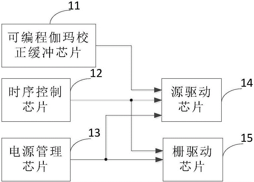
[0007] Because the existing drive circuit needs to set the programmable gamma correction buffer chip 11, thus increasing the production cost

Method used


Image

  • Driving circuit and liquid crystal display device
  • Driving circuit and liquid crystal display device
  • Driving circuit and liquid crystal display device

Examples


Embodiment Construction

[0041] The following descriptions of the various embodiments refer to the accompanying drawings to illustrate specific embodiments in which the present invention can be practiced. The directional terms mentioned in the present invention, such as "up", "down", "front", "back", "left", "right", "inside", "outside", "side", etc., are for reference only The orientation of the attached schema. Therefore, the directional terms used are used to illustrate and understand the present invention, but not to limit the present invention. In the figures, structurally similar units are denoted by the same reference numerals.

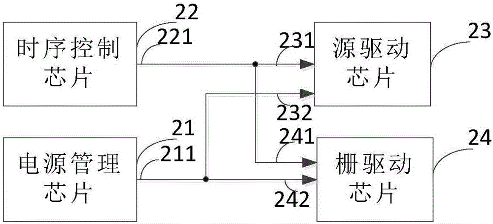
[0042] Please refer to figure 2 , figure 2 It is a structural schematic diagram of the driving circuit of the present invention.

[0043] Such as figure 2 As shown, the driving circuit of the present invention includes: a power management chip 21 , a timing control chip 22 and a source driving chip 23 . The power management chip 21 is used to generate a data c...


PUM


Abstract

The invention provides a driving circuit and a liquid crystal display device. The driving circuit comprises a power management chip, a timing sequence control chip and a source driving chip, wherein the power management chip is used for generating data control voltage; the timing sequence control chip is used for providing a first timing sequence control signal and a video signal; the source driving chip is used for converting the video signal into a plurality of gray-scale voltages, pre-obtaining a relation between brightness of a display panel and gray scale and a relation between the brightness of the display panel and the voltage under a preset gamma curve, obtaining a relation between the gray scale and the voltage after dividing voltage according to the relation between brightness of the display panel and gray scale and the relation between the brightness of the display panel and the voltage, obtaining a resistance string value according to the relation between the gray scale and the voltage after dividing voltage, and generating data signals according to the data control voltage, the first timing sequence control signal, the video signal and the resistance string value to enable the display effect of the panel to meet a preset condition. Through the driving circuit and the liquid crystal display device, the production cost can be reduced.

Description

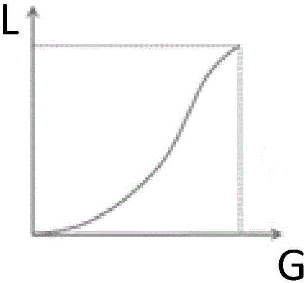
[0001] 【Technical field】 [0002] The invention relates to the technical field of displays, in particular to a driving circuit and a liquid crystal display device. [0003] 【Background technique】 [0004] At present, the driving circuit of the liquid crystal display panel includes: a programmable gamma correction buffer chip 11, a timing control chip 12, a power management chip 13, a source driver chip 14 and a gate driver chip 15; wherein, the programmable gamma correction buffer chip 11 is used for Provide reference voltages to the source driver chip 14. Generally, 14 gray-scale reference voltages are required between 0 and 14V, with half positive and negative polarities. Generally, the reference voltages are gray scales 0, 1, 31, 127, 223, 254, and 255. . [0005] The gray scale and brightness of the panel need to meet a certain relationship curve to achieve the best visual effect of the human eye. Usually, when the gamma value is 2.2, the visual effect is the best. [000...

Claims


Application Information

Patent Timeline
Patent Type & Authority Applications(China)
IPC IPC(8): G09G3/36
CPCG09G3/36G09G3/3611G09G3/3696G09G2320/0673G09G2320/0276G09G2330/021G09G3/3685G09G2310/08G09G3/3674G09G3/2007G09G2320/0666
Inventor 陈宥烨何振伟吴宇何涛
Owner TCL CHINA STAR OPTOELECTRONICS TECH CO LTD
Learn More